
| A Pathology of Modern Cabling |
| Originally published March, 1998 |
| by
Carlo Kopp |
| © 1998, 2005 Carlo Kopp |
The network is down ! Let's panic ! Let's run around in circles aimlessly and unplug and plug in every machine ... Does this sound familiar ? Almost every site has had this type of experience at some time in its history, and needless to say it usually results in much unproductive time and diminished profit margins. Is this an unavoidable state of affairs ? Hardly. A systematic approach to debugging network and other cabling problems not only exists, but is readily available to any site administrator, or other party presented with the horrors of a broken network or machine to peripheral connection. In many instances, the application of even simple logic with a little knowledge can enable the rapid resolution of most such problems, certainly those associated with the cabling infrastructure. In this month's tutorial we will take a look at the basic types of problem which can occur in copper and fibre cables, and we will look at some basic strategies for isolating and removing the cause of the problem. The best starting point for such a discussion is to take a look at the most common failure modes in various types of networking hardware, and explore some of the implications of these. Failure Modes in Cables and Connectors The cable is the medium via which networking traffic is distributed between machines, a bland statement but one with important implications. For a cable to perform this function it must provide a working electrical or optical transmission environment, ie it must carry signals without undue distortion in shape, timing, amplitude (ie strength) and it must be relatively clean of interfering signals. Violate any of these conditions and trouble will occur sooner or later. Shape distortion is a problem endemic to copper cables, and results from a loss of useful cable bandwidth. Shear off the upper harmonics and a nice trapezoidal pulse train becomes a series of ugly bumps, which most receivers will not recognise as a pulse train. This problem occurs most often due to aging or due to water or moisture penetration into the cable dielectric. The fix is to isolate the bad piece of cable and excise it. Timing problems result very commonly from the very common bad habit of incrementally extending networks beyond their standards mandated segment lengths, or by adding in more repeaters than allowed. In either case the broadcast mechanism for collision detection is compromised as a result of which packets may overlap, trash one another and become lost. This type of problem can be quite insidious, since it will not be seen at low traffic levels but suddenly pops up when a heavy burst of traffic occurs. Of course, once the traffic load drops, the problem disappears. The fix to this problem is to repartition the network differently, ensuring that segment propagation delays are compliant with the standard. Prevention is of course much easier than detection and repair, however in many sites which have grown incrementally, extended in turn by different parties each with a limited knowledge of the topology, this can be difficult to control. Amplitude problems, also known as signal loss or attenuation problems, result from situations where the signal loss in the cable is such that what a receiver sees is much to faint to resolve cleanly into pulse trains of data. There are two most frequent causes of this. The first is cable degradation, detailed above, resulting in signal loss. The second most frequent cause is excessive length of cable segments, which may be within the bounds of timing but not within the bounds of cable loss performance (ie dB/km) for the cable type in use. A classical scenario of this ilk is the other bad habit of using 10-Base-2 thinwire RG-58 cable beyond its nominal 200 metre segment length, to say 300, 400 or 500 metres. Often also injudicious choice of cheap and nasty manufacturer X's cable may produce exactly the same result with perfectly "legal" cable lengths. Interfering signals is another interesting problem, the most frequent causes of which are crosstalk and reflections. Crosstalk results form signals electromagnetically coupling into your networking cable from an adjacent cable, and can be a problem especially where you are trying to mix different signal types. Twisted pair cables, despite their good common mode immunity, can experience such problems. Reflections are in a class of their own, and are a fact of life with either copper or optical cables. The basic physics of all wave propagation mean that any change in the electrical (or optical) properties of the medium will cause part of the impinging signal to be reflected back to the source and part to propagate onward. Essentially the energy of a pulse (or signal) is split into a reflected and a propagating component. The reflected component of course adds or subtracts to/from the real signal and reduces the useful noise margin of the cable, ie the separation between what we want and what we don't want. There are several common causes of reflections in copper cables. The first is the use of inhomogeneous cable types in a single segment, each will have its own characteristic electrical impedance, and if these are beyond the limits allowed by the applicable standard, the ratio of signal to reflections may cross a safe limit and packets will be lost. Again this can be a problem with very cheap and nasty cables, since their adherence to nominal specs may not be very good. Standards such as Ethernet/802.3 impose fairly tight but reasonable limits on cable electrical performance. Those who fail to observe this will suffer accordingly. Another cause of reflections are kinks, tight bends, or crushing in a cable which distort its shape to the point where its impedance changes enough to produce significant reflections. Treat the cable with contempt and it will bite back in its own way. The fix is again to excise the offending piece of cable. Optical cables are not immune to such problems, although their point-to-point nature reduces their sensitivity to some of these effects. The most common problem is a kink in the cable which strains the fibre and causes light to spill out of the "bend", resulting in a signal loss problem. Bad connectors can also cause much trouble. There are several modes in which connectors can fail. Th most frequent mode is an open circuit, where the cable becomes detached internally from the connector. Since such problems are often intermittent, physically moving the connector can hide the problem. Open circuits are common with solid core coaxial cables and twisted pair cables. Short circuits are also common with coaxial cable types, where improper cable installation traps strands of the woven shield inside the connector, allowing them to touch the core and short it out. Again, intermittency can be a frequent feature of such faults. Connectors can also produce lesser degradation of cable performance, by introducing reflections. Common causes are impedance mismatches resulting from the use of cheap garbage connectors, but also poor connector installation in which the cable is crushed. This can be common with crimped coaxial connectors. Excessive use ie connection and disconnection of a connector pair can also produce intermittent open circuits, should the connector pin(s) and mating receptacles become sufficiently worn, mechanically tired or contaminated with dust, dirt or lint. Getting contaminants into electrical or optical connectors is not a good idea, needless to say, and should be carefully avoided. In coaxial cabling schemes, terminators can be subject to the same failure modes as connectors, in addition to a propensity in cheap products to alter the termination impedance value with time (ie age or even disintegrate internally). The humble cable, despite its conceptual simplicity, can be a fragile conduit if not treated with respect, and the costs in downtime often greatly outweigh any time or money to be saved by buying cheap junk, or delegating the installation to unqualified staff or those with little respect for workmanship and quality. While networks are most vulnerable to large scale downtime resulting from cabling problems, the potential for serious downtime also exists with computer room cabling, and in the instance of critical single point of failure workstations or servers, also machine to peripheral problems. 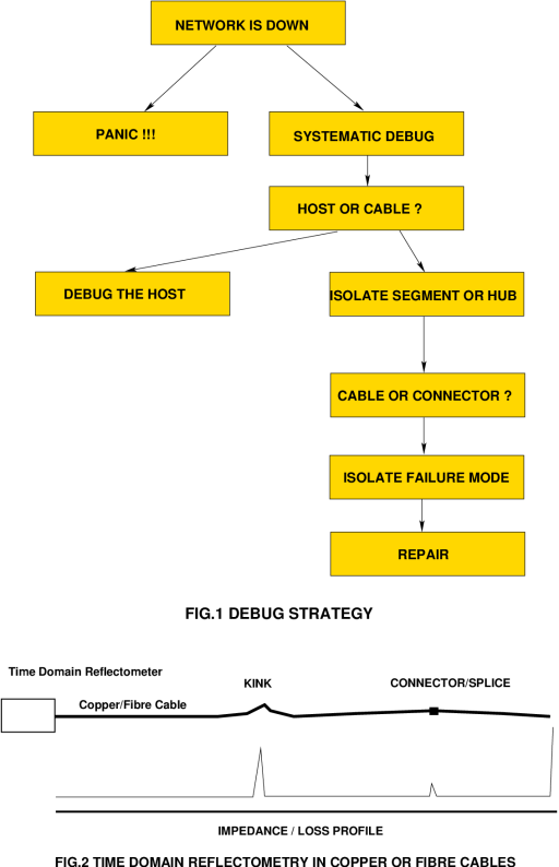 Isolating the Cable Problem What strategy best to use to find the problem ? Clearly dancing in a circle chanting incantations at the abberant cabling birdsnest seldom if ever yields the desired result, unless the resulting vibration and shock closes an open circuited connector ! On a more serious note, the best strategy is clearly dependent upon the specific type of cable installation and its most likely mode of failure. The starting point for this discussion is finding problems in coaxial cables. While coax is not currently the flavour of the month in LANs, it can still be found on many sites as part of older installations, and will be a feature of many Fibre Channel sites in the future. Since it can also be found between machines and monitors, radio LAN antenna to interface connections, or other peripherals from time to time, it is vital to know how to isolate coax problems. The typical symptom is a loss of signal quality or loss of signal altogether. In simple cabling schemes, such as device to device connections using a single piece of cable, the simplest isolation strategy is to simply take a known tested piece of cable of suitable length and bypass the suspect or known to be broken cable segment. The simplest test for a piece of coax is to take an Ohmmeter or cable tester, and check for a short between the core and shield, and for an open circuit between the cores at either end, and shields at either end. If the problem goes away with a bypass, we can then try the same test on the suspect cable to determine whether it has failed "hard" or is intermittent. A good test for intermittency is to tug the connectors, rotate them, or bend the cable at the connector. If the suspect cable proves to be dead, it can be either re-terminated if the problem is connector related, or replaced. Coaxial LANs using "backbone" Ethernet (10-Base-5) or thinwire Ethernet (10-Base-2) are much trickier, since they typically use several pieces of cable per segment, with a connector pair per each join, and terminators at either end. Thinwire includes T-pieces along the way to hang hosts off, while backbone uses vampire taps which involve a bored hole through the shield and dielectric, and a pin which taps the core. Because a failure in a LAN can result from other causes, such as jabbering hosts with broken interfaces, some care should be taken with initial diagnosis. The starting point therefore is to separate by disconnection the segments in the network which share common timing, ie are connected electrically or via repeaters. At some point in this incremental process, part of the network will come to life, while the other remains failed. The simpleminded way of doing this is to start at one end and move along, connector by connector (or T-piece), splitting the network and attaching a terminator to each of the now "sub-segments". A good technique for seeing whether you have network function is to fire up ping between a pair of machines at one extremity of the segment. When you have disconnected the sick end, ping will work. In this fashion, you can then systematically split the network into chunks which are either known to be broken or known to be working, and in some topologies, even restore partial function in the process. Once you have found the offending piece of cable, or connector/T-piece, you can either replace it or repair it. Many times the evidently misbehaving piece of cable will be embedded in a wall or ceiling or be otherwise difficult to replace or access, especially if it is a fairly long piece. Under such conditions it might be worth trying to isolate the failure point within the cable. A good tool for this purpose is the Time Domain Reflectometer (TDR), a device which fires a short pulse (or rather series of timed pulses) into the cable and looks at the energy bounced back. TDRs can locate shorts or impedance changes up to hundreds of yards along a cable. Where there is no obvious dead chunk of cable or connector/T-piece or terminator, then it might be worth using a TDR to analyse the whole cable segment. To do this, all hosts should be disconnected (so as not to add spurious electrical signals and loads to the cable), and the TDR used from one end of the cable to produce a plot of cable impedance (and shorts/opens) along its complete length. I can recall at least one time when this method nailed a bad piece of coax buried in a wall. Its impedance was so badly out that it produced enough reflection to create periodic but intermittent problems. More sophisticated problems such as jabbering hosts can also be isolated by splitting segments. Twisted pair networks are essentially immune from shared cable problems of the coaxial variety, since the cable is used in a point-to-point arrangement with devices connected at either end. Most decent hubs, repeaters, bridges and other multiple port devices have diagnostic LEDS on each port, which can indicate a loss of signal (whatever the cause) for each and every port. Twisted pair devices, if built properly, implicitly isolate signal problems to individual ports. Since typically a star/tree structure is used for a topology, it is very easy to split a misbehaving subtree of a network into separate components to isolate more subtle problems, including sick devices. The popularity of twisted pair schemes such as 10-Base-T, 100-Base-T and their various proprietary clones testify to the simplicity of debugging which comes with the separation of a network via multiport distribution devices, and associated patch panels. Optical cables, used either for point-to-point links or networks, are not immune from problems. The most frequent points of failure are connectors and patchcords from panels or wall sockets to equipment. A common problem can be connector contamination. A fully optical LAN, a relatively rare beast in this country, will employ a hierarchical star/tree topology like a twisted pair network, and good quality equipment will include signal activity or quality diagnostic LED indicators for each port on a distribution device. Therefore isolation of the misbehaving section of cable follows the same caveats as with twisted pair networks. Once the sick section is found, patchcords/connectors can be isolated by substitution using a known and trusted patchcord. Should the problem be within a section of cable, an Optical TDR (O-TDR) can be used to pinpoint whether it is in a termination or within the cable. Cabling alas is a necessary evil which we must live with in this industry. The problem will not go away, indeed with the into Gigabit bandwidths, using either fibre or copper, many of the more subtle problems described here will become more frequent and more debilitating in their effects. With increasing signal speeds, impedance mismatch problems, cable performance and connector performance all become potential killers, in the same manner as short and open circuits are in "low speed" networks or device to device connections. Having a good grasp of the likely failure modes in your hardware, and understanding systematic isolation techniques, will both become all the more important with the next generation of equipment. Those who choose to ignore this will pay the inevitable price. |
| $Revision: 1.1 $ |
| Last Updated: Sun Apr 24 11:22:45 GMT 2005 |
| Artwork and text © 2005 Carlo Kopp |