Templates
While expression based attribute values obviate the need for
script to generate base SVG elements, defining non-SVG namespaced
elements to instantiate these objects is still handy. In CSVG
one can use templates to define the content that is to be rendered
in place of the custom element. The RCC-XSLT syntax proposed in
the SVG 1.2 working draft is used.
Why use XSLT?
There are a couple of reasons why XSL templates should be used as
the prototyping mechanism for CSVG. Firstly, it is a widely used
language for specifying transformations from one XML grammar to
another. Rendering custom content is exactly this problem. XSLT,
being XML, is easily integrated into an SVG document. Its
declarative nature is more easily processed by a user agent than
free form script.
The issue of shadow tree regeneration is an important one. With
script based RCC, the author must explicitly control when and
how the shadow tree is to be regenerated. This will mostly be
by attaching DOM mutation event handlers to the custom element.
Because the initial
shadow tree generation is done using script it is difficult for
the user agent to analyse it to determine the minimum changes
necessary, automatically. When XSLT and constraints are used,
the constraints can be set up to depend on the custom element's
attributes, so that changes to the custom element will automatically
result in an update in the shadow tree.
Animation could also be specified on custom elements,
something which cannot be done with current RCC. Elements in the
shadow tree could have attributes which depend on animated attributes of
the custom elements, resulting in much more flexibility in animation
over what is current possible.
Template examples
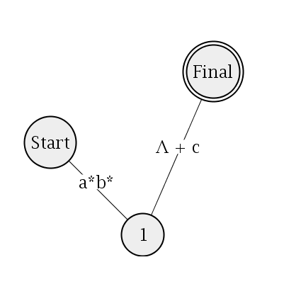
Here is an example for specifying nodes, arcs and labels in an
undirected graph.
This example, graph.svg, will have a list
of ex:node elements which specify the coordinates of the
node and also the label which will be displayed on the node.
Corresponding ex:arc elements will be used to specify
lines to be drawn between particular nodes. These arcs also have
labels.
<ex:graph>
<ex:node name="n1" cx="70" cy="200" label="Start"/>
<ex:node name="n2" cx="200" cy="330" label="1"/>
<ex:node name="n3" cx="300" cy="100" label="Final" final="true"/>
<ex:arc from="n1" to="n2" label="a*b*"/>
<ex:arc from="n2" to="n3" label="Λ + c"/>
</ex:graph>
The ex:arc elements use a string to refer to the ID of
the nodes the arc is to connect.
<xsl:template match="ex:graph">
<xsl:copy-of select="ex:arc"/>
<xsl:copy-of select="ex:node"/>
</xsl:template>
The ex:graph element here is just a container for the
ex:node and ex:arc elements. It makes sure
though that the arcs are rendered before the nodes, so that the
lines do not appear over the top of the circles.
<xsl:template match="ex:node">
<c:variable name="cx" value="c:Length(c:instance()/@cx)"/>
<c:variable name="cy" value="c:Length(c:instance()/@cy)"/>
<c:variable name="final" value="string(c:instance()/@final) = 'true'"/>
<c:variable name="b" value="c:bbox(following-sibling::svg:text)"/>
<circle r="0" fill="white" stroke-width="2" stroke="black">
<c:constraint attributeName="cx" value="$cx"/>
<c:constraint attributeName="cy" value="$cy"/>
<c:constraint attributeName="r" value="c:max(c:width($b) div 2 + 10, 30) + 5"/>
<c:constraint attributeName="display" value="c:if($final, 'inline', 'none')"/>
</circle>
<circle r="0" fill="#eee" stroke-width="2" stroke="black">
<c:constraint attributeName="cx" value="$cx"/>
<c:constraint attributeName="cy" value="$cy"/>
<c:constraint attributeName="r" value="c:max(c:width($b) div 2 + 10, 30)"/>
</circle>
<text text-anchor="middle">
<c:constraint attributeName="x" value="$cx"/>
<c:constraint attributeName="y" value="$cy + c:height($b) div 2"/>
<xsl:value-of select="@label"/>
</text>
</xsl:template>
The shadow tree for the ex:node element is reasonably simple.
First, it defines a few CSVG variables to hold information given
in the ex:node's attributes. Defined also is b
which holds the bounding box of the node's
label. If the label would extend past the edge of the default 30
radius circle, the size of the circle is increased. This is done
using the c:max function in the r attribute of the two
circles in the template.
The first circle is an outer ring for those nodes which are
marked as "final". It has a constraint on the display attribute which will
prevent it from beind rendered if the node is not a final node.
Finally there is the text element into which is copied the
label specified on the ex:node element.
<xsl:template match="ex:arc">
<c:variable name="from" value="c:instance()/@from"/>
<c:variable name="to" value="c:instance()/@to"/>
<c:variable name="x1" value="c:Length(c:instance()/../ex:node[@name=$from]/@cx)"/>
<c:variable name="y1" value="c:Length(c:instance()/../ex:node[@name=$from]/@cy)"/>
<c:variable name="x2" value="c:Length(c:instance()/../ex:node[@name=$to]/@cx)"/>
<c:variable name="y2" value="c:Length(c:instance()/../ex:node[@name=$to]/@cy)"/>
<line x1="0" y1="0" x2="0" y2="0" stroke="black" stroke-width="1">
<c:constraint attributeName="x1" value="$x1"/>
<c:constraint attributeName="y1" value="$y1"/>
<c:constraint attributeName="x2" value="$x2"/>
<c:constraint attributeName="y2" value="$y2"/>
</line>
<c:variable name="midx" value="($x1 + $x2) div 2"/>
<c:variable name="midy" value="($y1 + $y2) div 2"/>
<c:variable name="b" value="c:bbox(following-sibling::svg:text)"/>
<rect width="0" height="0" fill="white">
<c:constraint attributeName="x" value="c:x($b) - 1"/>
<c:constraint attributeName="y" value="c:y($b) - 1"/>
<c:constraint attributeName="width" value="c:width($b) + 2"/>
<c:constraint attributeName="height" value="c:height($b) + 2"/>
</rect>
<text text-anchor="middle">
<xsl:value-of select="@label"/>
<c:constraint attributeName="x" value="$midx"/>
<c:constraint attributeName="y" value="$midy"/>
</text>
</xsl:template>
The template for the ex:arc element is similar. Note that
the x1, y1, x2 and y2 variables (defining
the start and end coordinates of the arc) use the c:instance
function to access the custom element which instantiated this
shadow tree. XPath is then used to select the sibling ex:node
element so the strat and end coordinates can be found.
After the CSVG variable definitions the line element
which is the arc is copied to the shadow tree. Finally, a text
element is used to display the arc label. A white rect is
drawn just before this to make sure the label is legible over the
line.
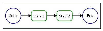
The next example is a translation of the
RCC
flowchart example from the SVG 1.2 working draft.
<ex:flowChart x="10" y="100" width="380" height="100">
<ex:terminalNode>
</ex:terminalNode>
<ex:processNode>
</ex:processNode>
<ex:processNode>
</ex:processNode>
<ex:terminalNode>
</ex:terminalNode>
</ex:flowChart>
flowchart.svg has an ex:flowchart
element which contains a series of ex:processNode and ex:terminalNodes.
<xsl:template match="ex:flowChart">
<c:variable name="x" value="c:Length(c:instance()/@x)"/>
<c:variable name="y" value="c:Length(c:instance()/@y)"/>
<c:variable name="width" value="c:Length(c:instance()/@width)"/>
<c:variable name="height" value="c:Length(c:instance()/@height)"/>
<rect width="0" height="0" fill="none" stroke="blue" stroke-width="1">
<c:constraint attributeName="x" value="$x"/>
<c:constraint attributeName="y" value="$y"/>
<c:constraint attributeName="width" value="$width"/>
<c:constraint attributeName="height" value="$height"/>
</rect>
<xsl:copy-of select="ex:*"/>
</xsl:template>
The template first declares a few CSVG variables for the attributes
given on the outer ex:flowchart element which specify
the dimensions of the object. A rect is then drawn to
show the outline of the flowchart. As in the graph example,
the child custom elements (the ex:processNode and
ex:terminalNodes) are copied into the ex:flowchart's
shadow tree, upon which these node elements will have their own
shadow trees generated.
<xsl:template match="ex:terminalNode">
<c:variable name="pos" value="count(c:instance()/preceding-sibling::ex:*)"/>
<c:variable name="num" value="count(c:instance()/../ex:*)"/>
<c:variable name="step" value="($width - 80) div ($num - 1)"/>
<c:variable name="cx" value="$x + 40 + $pos * $step"/>
<c:variable name="cy" value="$y + $height div 2"/>
<circle r="30" stroke-width="2" stroke="navy" fill="none">
<c:constraint attributeName="cx" value="$cx"/>
<c:constraint attributeName="cy" value="$cy"/>
</circle>
<text text-anchor="middle" font-size="14">
<c:constraint attributeName="x" value="$cx"/>
<c:constraint attributeName="y" value="$cy + c:height(c:bbox(.)) div 2"/>
<xsl:value-of select="text()"/>
</text>
<line x1="0" y1="0" x2="0" y2="0" stroke-width="2" stroke="black" marker-end="url(#Triangle)">
<c:constraint attributeName="x1" value="$cx + 30"/>
<c:constraint attributeName="y1" value="$cy"/>
<c:constraint attributeName="x2" value="$cx + $step - 40"/>
<c:constraint attributeName="y2" value="$cy"/>
<c:constraint attributeName="display" value="c:if($pos + 1 != $num, 'inline', 'none')"/>
</line>
</xsl:template>
The templates for the ex:processNode and ex:terminalNodes
are reasonably similar. Shown here is the code for the ex:processNodes.
The differ only in that for process nodes a circle is drawn,
for terminal nodes, a circle. Both of these are
positioned to be layed out horizontally, one after the other. Their
x coordinates depend on the cx CSVG variable, which calculates
the horizontal position using the current position number $pos
(just the count of how many node elements precede the current one in
the document tree), and the step variable, which is the amount
of horizontal space to leave between each node.
Next, a text is placed
in the middle of the node. Its content is selected from the character
content of the ex:terminalNode or ex:processNode
that is currently being processed. Finally, a line is
added to the shadow tree. Its display property is constrained
to be displayed only if this node isn't the last in the
flowchart.
The script in the RCC example does essentially the same thing
as this template. It loops over the node elements to calculate
the the total width and the positioning of the nodes and then
copies the SVG objects into the shadow tree for them to be
rendered. The RCC example cannot handle updates to the
custom elements, though. This type of functionality is currently
not built in to RCC, so the author must explicitly attach DOM
event handlers so that script can be run when the subtree is
modified. This could could simply re-run the function which
generated the shadow tree in the first place, but this will probably
be inefficient if only a small change was made. If the author
wants to make only the necessary changes, they must keep a track
of the dependencies in their code manually. In the CSVG solution,
this dependency tracking and update propagation is handled automatically.
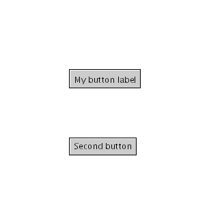
Say that we want to make a simple button widget. This button
should just be a rect with some text centered on it. The button
also should be able to run some user specified code when it is clicked.
To generate the buttons in this example, button.svg,
we need three things — the template definition, the template
instantiation elements and the script to handle the behaviour of
the buttons.
<script type="text/ecmascript">
<![CDATA[
function f() {
window.alert("Button click handler");
}
]]>
</script>
<ex:button x="100" y="100" onbuttonclick="f()">
</ex:button>
<ex:button x="100" y="200" onbuttonclick="f()">
</ex:button>
Here we have two custom elements to insert buttons into the
document. The ex namespace is declared on the root
svg element earlier in the document. The ex:button
elements have attributes for the coordinates at which to place
the button and an event handler to have some script run when
the button is clicked. The text inside the element will be used
as the button's label.
<xsl:template match="ex:button">
<c:variable name="gap" value="8"/>
<c:variable name="x" value="c:Length(c:instance()/@x)"/>
<c:variable name="y" value="c:Length(c:instance()/@y)"/>
<c:variable name="b" value="c:bbox(following-sibling::svg:text)"/>
<c:variable name="w" value="c:width($b)"/>
<c:variable name="h" value="c:height($b)"/>
<rect width="0" height="0" stroke="black" stroke-width="1" fill="#ccc" onclick="{@onbuttonclick}" onmouseover="testButtonMouseOver(evt)" onmouseout="testButtonMouseOut(evt)" onmousedown="testButtonMouseDown(evt)" onmouseup="testButtonMouseOut(evt)">
<c:constraint attributeName="x" value="$x"/>
<c:constraint attributeName="y" value="$y"/>
<c:constraint attributeName="width" value="$w + $gap * 2"/>
<c:constraint attributeName="height" value="$h + $gap * 2"/>
</rect>
<line stroke-width="1" stroke="white" pointer-events="none">
<c:constraint attributeName="x1" value="$x + 1"/>
<c:constraint attributeName="y1" value="$y + 1"/>
<c:constraint attributeName="x2" value="$x + $w + $gap * 2 - 1"/>
<c:constraint attributeName="y2" value="$y + 1"/>
</line>
<line stroke-width="1" stroke="white" pointer-events="none">
<c:constraint attributeName="x1" value="$x + 1"/>
<c:constraint attributeName="y1" value="$y + 1"/>
<c:constraint attributeName="x2" value="$x + 1"/>
<c:constraint attributeName="y2" value="$y + $h + $gap * 2 - 1"/>
</line>
<text font-size="12" pointer-events="none">
<c:constraint attributeName="x" value="$x + $gap"/>
<c:constraint attributeName="y" value="$y + $h + $gap"/>
<xsl:value-of select="text()"/>
</text>
</xsl:template>
The template element defines what content will be used as the
shadow tree for the ex:button element. The template starts
with a few
CSVG variable elements. The x and y variables
use the c:instance function to get the x and
y attribute values from the ex:button element which
instantiated the template.
The w and h variables will store the width and height
of the text label of the button.
Next is the rect which makes up the base of the button. Its
x, y, width and height attributes are
written in terms of the variables defined above it. Event handlers
are assigned to control the behaviour of the button. Following the
rect is a couple of lines to give the button a three dimensional look.
Finally in the template there is the text element which is
used for the button label. The content of the text element
is generated using the XSLT value-of element to select the
text nodes which are children of the ex:button element.
Notice that the rect's onclick event attribute gets its
content from the onbuttonclick of the custom element. In the example
here, this is all that is needed for a custom event to be supported.
In more complex situations, it may be necessary to synthesize an event
in script.
<script type="text/ecmascript">
<![CDATA[
function testButtonMouseOver(evt) {
System.out.println("mouse over");
evt.target.setAttributeNS(null, "fill", "#ddd");
}
function testButtonMouseOut(evt) {
System.out.println("mouse out");
evt.target.setAttributeNS(null, "fill", "#ccc");
}
function testButtonMouseDown(evt) {
evt.target.setAttributeNS(null, "fill", "#aaa");
}
]]>
</script>
The script here handles the behaviour for the button widget. When
the mouse is moved over or clicked on the button, the rect
in the shadow tree is modified to make its colour change.
Constraint propagation will occur if the attributes of the
custom elements are modified. If an element in the
shadow tree uses the c:instance() function to refer
to a value on the custom element, this value will be updated in
the shadow tree automatically, just like for non-templated elements.
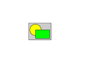
The button example can be extended to allow arbitrary SVG content as
the button's label.
<ex:complexButton x="100" y="80" onbuttonclick="f()">
<circle cx="20" cy="20" r="20" fill="yellow" stroke="black" stroke-width="1"/>
<rect x="20" y="20" width="50" height="30" fill="lime" stroke="black" stroke-width="1"/>
</ex:complexButton>
This example, complexButton.svg,
uses a circle and a rect as the button's label.
Only a small modification to the template used in the previous example
is needed to handle this.
<xsl:template match="ex:complexButton">
<c:variable name="gap" value="4"/>
<c:variable name="x" value="c:Length(c:instance()/@x)"/>
<c:variable name="y" value="c:Length(c:instance()/@y)"/>
<c:variable name="b" value="c:bbox(following-sibling::svg:g)"/>
<c:variable name="w" value="c:width($b)"/>
<c:variable name="h" value="c:height($b)"/>
<rect width="0" height="0" stroke="black" stroke-width="1" fill="#ccc" onclick="{@onbuttonclick}" onmouseover="testButtonMouseOver(evt)" onmouseout="testButtonMouseOut(evt)" onmousedown="testButtonMouseDown(evt)" onmouseup="testButtonMouseOut(evt)">
<c:constraint attributeName="x" value="$x"/>
<c:constraint attributeName="y" value="$y"/>
<c:constraint attributeName="width" value="$w + $gap * 2"/>
<c:constraint attributeName="height" value="$h + $gap * 2"/>
</rect>
<line stroke-width="1" stroke="white" pointer-events="none">
<c:constraint attributeName="x1" value="$x + 1"/>
<c:constraint attributeName="y1" value="$y + 1"/>
<c:constraint attributeName="x2" value="$x + $w + $gap * 2 - 1"/>
<c:constraint attributeName="y2" value="$y + 1"/>
</line>
<line stroke-width="1" stroke="white" pointer-events="none">
<c:constraint attributeName="x1" value="$x + 1"/>
<c:constraint attributeName="y1" value="$y + 1"/>
<c:constraint attributeName="x2" value="$x + 1"/>
<c:constraint attributeName="y2" value="$y + $h + $gap * 2 - 1"/>
</line>
<g pointer-events="none">
<c:constraint attributeName="transform" value="concat('translate(', $x + $gap, ',', $y + $gap, ')')"/>
<xsl:copy-of select="*"/>
</g>
</xsl:template>
In place of the text element there is an g element.
This is used to position the content over the button. The
transform attribute is used to specify a translation
in terms of the $x and $y variables.
The xsl:copy-of element is used to copy the children of the
ex:complexButton template instantiation elements to become
children of this g element.
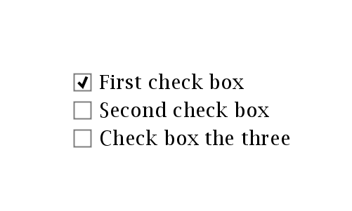
Another simple widget example is given here in
checkbox.svg.
Example 10 — Vertical layout container
Templates can be written to arrange SVG objects so that common
layout problems don't have to be handled explicitly. The first
layout example here is a vertical layout element, which arranges
its child elements in a column.
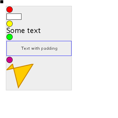
This example, vlayout.svg, uses a template to place each of the child elements
of the custom element at differing y coordinates.
<ex:vertical-layout id="one" x="20" y="20">
<circle cx="10" cy="10" r="10" fill="red" stroke="black" stroke-width="1"/>
<rect x="0" y="0" width="50" height="20" fill="white" stroke="black" stroke-width="1">
<c:constraint attributeName="height" value="$rectHeight"/>
</rect>
<circle cx="10" cy="10" r="10" fill="yellow" stroke="black" stroke-width="1"/>
<text x="0" font-size="24">
<c:constraint attributeName="y" value="c:height(c:bbox(.))"/>
Some text
</text>
<circle cx="10" cy="10" r="10" fill="lime" stroke="black" stroke-width="1"/>
<g>
<rect width="220" height="50" fill="none" stroke="blue" stroke-width="1"/>
<text x="50" y="30" text-align="middle">
</text>
</g>
<circle cx="10" cy="10" r="10" fill="#c08" stroke="black" stroke-width="1"/>
<path d="M 0 20 L 20 0 L 40 80 L 90 0 z" fill="#fc0" stroke="#c80" stroke-width="3"/>
</ex:vertical-layout>
The t:vertical-layout element just contains the SVG elements
which will be layed out. Since each element will be placed in a
g element which has been translated to the current position
in the column, each of the SVG elements here are placed close to (0, 0).
The text element, for example,
has its y attribute set so that the top of the text is aligned
with y=0.
<xsl:template match="ex:vertical-layout">
<c:variable name="x" value="c:Length(c:instance()/@x)"/>
<c:variable name="y" value="c:Length(c:instance()/@y)"/>
<c:variable name="origy" value="$y"/>
<c:variable name="maxw" value="0"/>
<rect width="0" height="0" fill="#eee" stroke="#ccc" stroke-width="1">
<c:constraint attributeName="x" value="$x - 1"/>
<c:constraint attributeName="y" value="$origy - 1"/>
<c:constraint attributeName="width" value="$finalmaxw + 3"/>
<c:constraint attributeName="height" value="$finaly - $origy"/>
</rect>
<xsl:for-each select="*">
<g>
<c:constraint attributeName="transform" value="concat('translate(', $x + 1, ',', $y + 1, ')')"/>
<xsl:copy-of select="."/>
</g>
<c:variable name="y" value="$y + c:height(c:bbox(preceding-sibling::svg:g[1])) + 3"/>
<c:variable name="maxw" value="c:max($maxw, c:width(c:bbox(preceding-sibling::svg:g[1])))"/>
</xsl:for-each>
<c:variable name="finaly" value="$y"/>
<c:variable name="finalmaxw" value="$maxw"/>
</xsl:template>
The template works by copying each of the child elements into
the shadow tree one by one. The xsl:for-each element
will iterate over each element. The current y coordinate and the
maximum width of the layout in each iteration are kept track of by
generating CSVG variable elements that build upon previous
variable elements with the same name. After the iteration,
two variables are defined for the final y and maximum width values,
which are used earlier in the template for the dimensions of the
rect that acts as the background colour for the layout widget.
The shadow tree for the t:vertical-layout element is shown below.
<c:variable name="x" value="c:Length(c:instance()/@x)"/>
<c:variable name="y" value="c:Length(c:instance()/@y)"/>
<c:variable name="origy" value="$y"/>
<c:variable name="maxw" value="0"/>
<rect width="0" height="0" fill="#eee" stroke="#ccc" stroke-width="1">
<c:constraint attributeName="x" value="$x - 1"/>
<c:constraint attributeName="y" value="$origy - 1"/>
<c:constraint attributeName="width" value="$finalmaxw + 3"/>
<c:constraint attributeName="height" value="$finaly - $origy"/>
</rect>
<g>
<c:constraint attributeName="transform" value="concat('translate(', $x + 1, ',', $y + 1, ')')"/>
<circle cx="10" cy="10" r="10" fill="red" stroke="black" stroke-width="1"/>
</g>
<c:variable name="y" value="$y + c:height(c:bbox(preceding-sibling::svg:g[1])) + 3"/>
<c:variable name="maxw" value="c:max($maxw, c:width(c:bbox(preceding-sibling::svg:g[1])))"/>
<g>
<c:constraint attributeName="transform" value="concat('translate(', $x + 1, ',', $y + 1, ')')"/>
<rect id="a" x="0" y="0" width="50" height="20" fill="white" stroke="black" stroke-width="1"/>
</g>
<c:variable name="y" value="$y + c:height(c:bbox(preceding-sibling::svg:g[1])) + 3"/>
<c:variable name="maxw" value="c:max($maxw, c:width(c:bbox(preceding-sibling::svg:g[1])))"/>
<g>
<c:constraint attributeName="transform" value="concat('translate(', $x + 1, ',', $y + 1, ')')"/>
<circle cx="10" cy="10" r="10" fill="yellow" stroke="black" stroke-width="1"/>
</g>
<c:variable name="y" value="$y + c:height(c:bbox(preceding-sibling::svg:g[1])) + 3"/>
<c:variable name="maxw" value="c:max($maxw, c:width(c:bbox(preceding-sibling::svg:g[1])))"/>
<g>
<c:constraint attributeName="transform" value="concat('translate(', $x + 1, ',', $y + 1, ')')"/>
<text x="0" y="c:height(c:bbox(.))" font-size="24">
</text>
</g>
<c:variable name="y" value="$y + c:height(c:bbox(preceding-sibling::svg:g[1])) + 3"/>
<c:variable name="maxw" value="c:max($maxw, c:width(c:bbox(preceding-sibling::svg:g[1])))"/>
<g>
<c:constraint attributeName="transform" value="concat('translate(', $x + 1, ',', $y + 1, ')')"/>
<circle cx="10" cy="10" r="10" fill="lime" stroke="black" stroke-width="1"/>
</g>
<c:variable name="y" value="$y + c:height(c:bbox(preceding-sibling::svg:g[1])) + 3"/>
<c:variable name="maxw" value="c:max($maxw, c:width(c:bbox(preceding-sibling::svg:g[1])))"/>
<g>
<c:constraint attributeName="transform" value="concat('translate(', $x + 1, ',', $y + 1, ')')"/>
<g>
<rect width="220" height="50" fill="none" stroke="blue" stroke-width="1"/>
<text x="50" y="30" text-align="middle">
</text>
</g>
</g>
<c:variable name="y" value="$y + c:height(c:bbox(preceding-sibling::svg:g[1])) + 3"/>
<c:variable name="maxw" value="c:max($maxw, c:width(c:bbox(preceding-sibling::svg:g[1])))"/>
<g>
<c:constraint attributeName="transform" value="concat('translate(', $x + 1, ',', $y + 1, ')')"/>
<circle cx="10" cy="10" r="10" fill="#c08" stroke="black" stroke-width="1"/>
</g>
<c:variable name="y" value="$y + c:height(c:bbox(preceding-sibling::svg:g[1])) + 3"/>
<c:variable name="maxw" value="c:max($maxw, c:width(c:bbox(preceding-sibling::svg:g[1])))"/>
<g>
<c:constraint attributeName="transform" value="concat('translate(', $x + 1, ',', $y + 1, ')')"/>
<path d="M 0 20 L 20 0 L 40 80 L 90 0 z" fill="#fc0" stroke="#c80" stroke-width="3"/>
</g>
<c:variable name="y" value="$y + c:height(c:bbox(preceding-sibling::svg:g[1])) + 3"/>
<c:variable name="maxw" value="c:max($maxw, c:width(c:bbox(preceding-sibling::svg:g[1])))"/>
<c:variable name="finaly" value="$y"/>
<c:variable name="finalmaxw" value="$maxw"/>
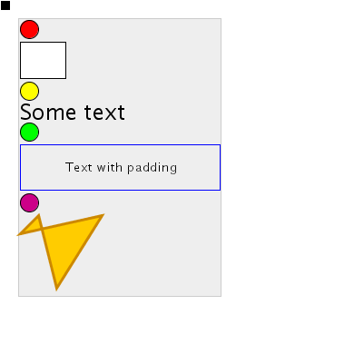
In this example clicking on the black rectangle in the upper right
corner will increase the height attribute of the white
rect. The objects below this rect will
be shifted down to accommodate the rect's new height.
Example 11 — Grid layout container
To lay out SVG objects in a grid is more complex. Many variables
must be set up to ensure the x coordinate of all cells in the one
column are equal, and the y coordinates of all cells in the one
row also.
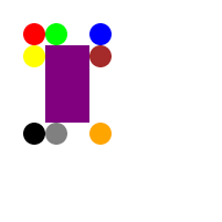
In this templated grid example, gridt.svg,
we want to be able to lay out objects in a grid with an arbitrary
number of rows and columns. We'll use a specification similar to
HTML tables, which uses one element to enclose the whole table,
one to enclose a row of elements and one to enclose one cell in a row.
<ex:grid x="20" y="20">
<ex:row>
<ex:cell>
<circle cx="10" cy="10" r="10" fill="red"/>
</ex:cell>
<ex:cell>
<circle cx="10" cy="10" r="10" fill="lime"/>
</ex:cell>
<ex:cell>
<circle cx="10" cy="10" r="10" fill="blue"/>
</ex:cell>
</ex:row>
<ex:row>
<ex:cell>
<circle cx="10" cy="10" r="10" fill="yellow"/>
</ex:cell>
<ex:cell>
<rect id="r" x="0" y="0" width="40" height="70" fill="purple" onclick="resizePurpleRect(evt)"/>
</ex:cell>
<ex:cell>
<circle cx="10" cy="10" r="10" fill="brown"/>
</ex:cell>
</ex:row>
<ex:row>
<ex:cell>
<circle cx="10" cy="10" r="10" fill="black"/>
</ex:cell>
<ex:cell>
<circle cx="10" cy="10" r="10" fill="gray"/>
</ex:cell>
<ex:cell>
<circle cx="10" cy="10" r="10" fill="orange"/>
</ex:cell>
</ex:row>
</ex:grid>
The template to position these objects correctly will need to iterate
over each t:cell and copy its contents into the shadow tree, wrapped
by an g element so it can be repositioned.
<xsl:template match="ex:grid">
<xsl:for-each select="ex:row">
<xsl:variable name="rp" select="position()"/>
<xsl:for-each select="ex:cell">
<g>
<c:constraint attributeName="transform" value="concat('translate(', $x{position()}, ', ', $y{$rp}, ')')"/>
<xsl:copy-of select="*"/>
</g>
<c:variable name="c{$rp}{position()}w" value="c:width(c:bbox(preceding-sibling::svg:g[1]))"/>
<c:variable name="c{$rp}{position()}h" value="c:height(c:bbox(preceding-sibling::svg:g[1]))"/>
</xsl:for-each>
</xsl:for-each>
The xsl:for-each element is used to iterate first over each
t:row in the grid. Each iteration, an XSLT variable is
defined to store the current row number. Note that this is not
a CSVG variable; this variable exists while processing the template
and is not copied into the shadow tree like CSVG variables are.
Inside this loop is another xsl:for-each to iterate over
each t:cell element in the current row. For each of these
cells, an g element is inserted into the shadow tree
containing the contents of the t:cell.
See that the the x and y attributes of the svg
element use braces to evaluate an expression at template processing
time. This is used here to construct the name of the variable
being referred to. So, the first cell in the grid will have its
g element with transform attribute transform="concat('translate(', $x1, ', ', $y1, ')')" and the
last cell will have transform="concat('translate(', $x1, ', ', $y1, ')')".
Following that, two CSVG variables are defined which will hold
the width and height of the current cell. Again, braces are used
to construct the variable anmes.
<xsl:for-each select="ex:row[position()=1]/ex:cell">
<xsl:variable name="cp" select="position()"/>
<xsl:variable name="value">
<xsl:text>
</xsl:text>
<xsl:for-each select="../../ex:row">
<xsl:if test="position() != 1">
</xsl:if>
<xsl:text>
</xsl:text>
<xsl:value-of select="$cp"/>
<xsl:value-of select="position()"/>
<xsl:text>
</xsl:text>
</xsl:for-each>
<xsl:text>
</xsl:text>
</xsl:variable>
<c:variable name="min{position()}w" value="{$value}"/>
</xsl:for-each>
<xsl:for-each select="ex:row">
<xsl:variable name="rp" select="position()"/>
<xsl:variable name="value">
<xsl:text>
</xsl:text>
<xsl:for-each select="ex:cell">
<xsl:if test="position() != 1">
</xsl:if>
<xsl:text>
</xsl:text>
<xsl:value-of select="position()"/>
<xsl:value-of select="$rp"/>
<xsl:text>
</xsl:text>
</xsl:for-each>
<xsl:text>
</xsl:text>
</xsl:variable>
<c:variable name="r{position()}h" value="{$value}"/>
</xsl:for-each>
The next task for the template is to generate variables which will
store the maximum width of the cells in each column. These
variables will be called min1w, min2w, etc. —
one for each column. This begins by iterating over each of the
cells in the first row of the grid. For each of these cells,
a CSVG variable is created. This variable should be equal
to a c:max function call of the width of the cell in each row.
The $value XSL variable is used here to construct the
complex value attribute for the c:variable. It will
generate an attribute with value max($c11w,$c12w,$c13w)
for the first column. Similarly for the other two columns.
The same thing is done for each row of the grid. Variables called
r1h, r2h, etc. are generated which hold the height
of each row.
<xsl:for-each select="ex:row[position()=1]/ex:cell">
<xsl:choose>
<xsl:when test="position()=1">
<c:variable name="x1" value="c:Length(c:instance()/@x)"/>
</xsl:when>
<xsl:otherwise>
<c:variable name="x{position()}" value="$x{position()-1} + $min{position()-1}w"/>
</xsl:otherwise>
</xsl:choose>
</xsl:for-each>
<xsl:for-each select="ex:row">
<xsl:choose>
<xsl:when test="position()=1">
<c:variable name="y1" value="c:Length(c:instance()/@y)"/>
</xsl:when>
<xsl:otherwise>
<c:variable name="y{position()}" value="$y{position()-1} + $r{position()-1}h"/>
</xsl:otherwise>
</xsl:choose>
</xsl:for-each>
Finally the template creates CSVG variables which store the x
coordinates of each column and the y coordinates of each row.
xsl:choose is used to create the variable x1
equal to the x attribute given on the t:grid
element, and other xn variables which are equal to
the previous x coordinate plus the width of the previous column.
It is these variables which are used on the g's transform
attribute at the start of the template.
The shadow tree that is finally generated in this example is shown
below.
<g>
<c:constraint attributeName="transform" value="concat('translate(', $x1, ', ', $y1, ')')"/>
<circle cx="10" cy="10" r="10" fill="red"/>
</g>
<c:variable name="c11w" value="c:width(c:bbox(preceding-sibling::svg:g[1]))"/>
<c:variable name="c11h" value="c:height(c:bbox(preceding-sibling::svg:g[1]))"/>
<g>
<c:constraint attributeName="transform" value="concat('translate(', $x2, ', ', $y1, ')')"/>
<circle cx="10" cy="10" r="10" fill="lime"/>
</g>
<c:variable name="c21w" value="c:width(c:bbox(preceding-sibling::svg:g[1]))"/>
<c:variable name="c21h" value="c:height(c:bbox(preceding-sibling::svg:g[1]))"/>
<g>
<c:constraint attributeName="transform" value="concat('translate(', $x3, ', ', $y1, ')')"/>
<circle cx="10" cy="10" r="10" fill="blue"/>
</g>
<c:variable name="c31w" value="c:width(c:bbox(preceding-sibling::svg:g[1]))"/>
<c:variable name="c31h" value="c:height(c:bbox(preceding-sibling::svg:g[1]))"/>
<g>
<c:constraint attributeName="transform" value="concat('translate(', $x1, ', ', $y2, ')')"/>
<circle cx="10" cy="10" r="10" fill="yellow"/>
</g>
<c:variable name="c12w" value="c:width(c:bbox(preceding-sibling::svg:g[1]))"/>
<c:variable name="c12h" value="c:height(c:bbox(preceding-sibling::svg:g[1]))"/>
<g>
<c:constraint attributeName="transform" value="concat('translate(', $x2, ', ', $y2, ')')"/>
<rect x="0" y="0" width="40" height="70" fill="purple" onclick="resizePurpleRect(evt)"/>
</g>
<c:variable name="c22w" value="c:width(c:bbox(preceding-sibling::svg:g[1]))"/>
<c:variable name="c22h" value="c:height(c:bbox(preceding-sibling::svg:g[1]))"/>
<g>
<c:constraint attributeName="transform" value="concat('translate(', $x3, ', ', $y2, ')')"/>
<circle cx="10" cy="10" r="10" fill="brown"/>
</g>
<c:variable name="c32w" value="c:width(c:bbox(preceding-sibling::svg:g[1]))"/>
<c:variable name="c32h" value="c:height(c:bbox(preceding-sibling::svg:g[1]))"/>
<g>
<c:constraint attributeName="transform" value="concat('translate(', $x1, ', ', $y3, ')')"/>
<circle cx="10" cy="10" r="10" fill="black"/>
</g>
<c:variable name="c13w" value="c:width(c:bbox(preceding-sibling::svg:g[1]))"/>
<c:variable name="c13h" value="c:height(c:bbox(preceding-sibling::svg:g[1]))"/>
<g>
<c:constraint attributeName="transform" value="concat('translate(', $x2, ', ', $y3, ')')"/>
<circle cx="10" cy="10" r="10" fill="gray"/>
</g>
<c:variable name="c23w" value="c:width(c:bbox(preceding-sibling::svg:g[1]))"/>
<c:variable name="c23h" value="c:height(c:bbox(preceding-sibling::svg:g[1]))"/>
<g>
<c:constraint attributeName="transform" value="concat('translate(', $x3, ', ', $y3, ')')"/>
<circle cx="10" cy="10" r="10" fill="gray"/>
</g>
<c:variable name="c33w" value="c:width(c:bbox(preceding-sibling::svg:g[1]))"/>
<c:variable name="c33h" value="c:height(c:bbox(preceding-sibling::svg:g[1]))"/>
<c:variable name="min1w" value="c:max($c11w,$c12w,$c13w)"/>
<c:variable name="min2w" value="c:max($c21w,$c22w,$c23w)"/>
<c:variable name="min3w" value="c:max($c31w,$c32w,$c33w)"/>
<c:variable name="r1h" value="c:max($c11h,$c21h,$c31h)"/>
<c:variable name="r2h" value="c:max($c12h,$c22h,$c32h)"/>
<c:variable name="r3h" value="c:max($c13h,$c23h,$c33h)"/>
<c:variable name="x1" value="c:Length(c:instance()/@x)"/>
<c:variable name="x2" value="$x1 + $min1w"/>
<c:variable name="x3" value="$x2 + $min2w"/>
<c:variable name="y1" value="c:Length(c:instance()/@y)"/>
<c:variable name="y2" value="$y1 + $r1h"/>
<c:variable name="y3" value="$y2 + $r2h"/>
In this example clicking on the purple rect in the centre of the
grid will cause its width or height to be increased. The rest
of the elements in the grid will move over appropriately as
the constraints are updated.
Last updated: 26th February, 2004