Setting up the photodiode.
The photodiode comes with online documentation, which includes a pin diagram (right).
In this case, there are nine pins on this diode, but only five of them are actually connected to anything!
There are four pins (one in each corner) corresponding to the anodes for each quadrant.
The anode is positive end of the diode, i.e., positive charge flows from the anode to the negative end (the cathode) when light is incident on the photodiode.
All four quadrants share a single common cathode (pin 3).
Solder wires to the five relevant connection.
Biasing the photodiode.
We are going to build a circuit to apply a bias voltage across the phtodiode.
There are two reasons for doing this.
The first reason is that we want to prevent charge buildup and leakage between quadrants.
If we hook up the anode and cathode from each quadrant directly to a measuring device (e.g., a scope), we will observe that a light on quadrant d creates a voltage in quadrant a.
This is not desirable as we want each quadrant to act as an independent measuring device.
The reason this happens is that the charge created from the photodiode must be efficiently removed or it will diffuse across quadrants and create a voltage in other quadrants.
When we hook up a scope to the photodiode, is does not provide a means for the charge to be removed from each quadrant, and so we observe leakage.
The solution to this conundrum is to build a circuit to keep the voltage across the photodiode fixed by whisking away any charge created by light incident on the photodiode.
We shall see how to do this below when we construct a feedback loop circuit.
The second reason for biasing the photodiode is that we want to ensure that it ensure that it is operating in what is known as a linear regime.
Fig. 2 is a plot of "dark current" vs. voltage for a photodiode.
The dark current is the amount of current, which leaks through the diode if there is a bias applied to it.
(This is different from the current, which is produced from light incident on the photodiode.)
We want to operate the photodiode so that the are operating with a negative potential difference across the diode, i.e., the diode is operating on the left-hand side of Fig. 2.
When the diode is operated this way, it is said to have a "reverse bias."
By operating with a reverse bias, we can stay away from the right-hand half of Fig. 2 where the dark current begins curving up and the curve becomes non-linear.
Non-linear response will make the photodiode circuit noisier.
The left-hand side, in contrast, has a straight curve, which means that the photodiode behaves like a resistor.
Why not operate the diode with zero bias?
Zero is still in the linear regime, so why bother to apply a reverse bias?
The answer to this question will become more clear below, but the short answer is that our readout circuit will have two different places where the voltage is approximately zero: ground and "digitial ground."
We can think of ground as the true ground: a 0V wire which is connected to the Earth where charge can be dissipated.
Digital ground, on the other hand, is maintained at approximately 0V by a feedback circuit.
Ostensibly, these two grounds are both at 0V, but digital ground will include fluctuations about the true ground.
This means that there will be some time dependent potential difference between ground and digital ground.
We would rather not have the difference between ground and digital ground flipping sign with every fluctuation in the digital ground.
To solve this, we use a reverse bias so that the potential difference across the diode is not given by the size of the fluctuations, but rather some fixed DC offset plus fluctuations.
This is a more stable configuration.
|
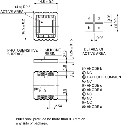
Fig 1: diagram of a quad photodiode.
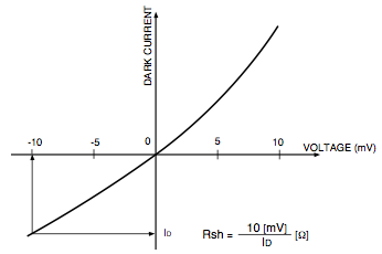
Fig 2: IV diagram for photodiode dark current.
|
A feedback loop circuit to maintain reverse bias.
Now we are going to cover how to build a circuit to maintain the reverse bias.
Here are a couple things to keep in mind when building your circuit.
First, use a breadboard to make it easy to test your circuit and make quick changes.
Second, take measures to avoid frying your electronics!
Build the circuit with the power off.
When you are ready to turn on the power, make sure the circuit is hooked up to a scope so you can tell right away if it works.
(You should be able to wave your hand in front of the photodiode, and the scope signal should go up and down with the varying light.)
If the circuit does not behave the way you think it should be behaving, turn off the power while you debug.
If you leave on the power for more than a few seconds, and the circuit is miswired, components can become dangerously hot and sustain permanent damage.
Fig. 3 is a diagram of the circuit we will be using to maintain a bias while reading out the current on the photodiode.
The small black triangle is the photodiode and the large triangle is the op-amp.
In a nutshell, here's what this circuit does.
When light is incident on the photodiode, charge flows off the cathode and into what's called the "inverting input" of the op-amp (marked with a minus sign).
The op-amp takes the signal from the inverting input and (as the name suggests) flips it.
It adds the inverted signal to the "non-inverting" signal from the "+" terminal and multiplies the sum by a factor called the "open loop gain."
Typcally, the open loop gain is a large number O(10K).
In this circuit, the non-inverting input is connected to true ground, so the only signal going into the op-amp is the signal from the cathode that enters the inverting input.
The amplified output signal emerges from the point of the triangle.
It goes back toward the cathode, dissipating power in the resistor, before connecting to the cathode.
This feedback loop has the effect of keeping the voltage near the cathode close to zero.
As soon as charge is released creating a small current, the op-amp flips the signal, amplifies it, and sends it back to the cathode to keep the voltage near zero.
This near-zero voltage is the digital ground.
Since the op-amp works to maintain the voltage across the photodiode fixed, the signal cannot be measured by looking at the voltage across the photodiode.
Instead, we measure the voltage across Vout and GND.
The signal strength in this circuit is given by i*R where i is the current flowing off of the photodiode and R is the resistor.
If you want to be able to adjust the amplitude of the amplifiaction, you can use a variable resistor.
And of course, since we are amplifying a signal with the op-amp, the op-amp must be powered.
It receives a +/-10V signal.
Finally, notice that anode is hooked up to the -10V lead.
This ensures that we maintain a reverse bias.
Why 10V?
Through trial and error, we found that voltages much higher than 10V cause (very loud) high-frequency resonant noise when laser light is incident on the photodiode.
Hooking up the op-amp.
To the unitiated, op-amps are less familiar electronic components than resistors or diodes, but it turns out they are pretty easy to understand.
They are typically housed in eight-pin computer chips.
Figs. 3 and 4 show diagrams for two different op-amps.
You should consult documentation for your own op-amp to see how it is wired.
(Also, note that most op-amps have a little circle on one end to tell you which way is up.)
We have already talked about three of the pins on the op-amp: the inverting and non-inverting input and the output.
The other two pins we need to know about here are -V and +V, which are used to provide power for the op-amp.
Fig. 4 shows a dual-channel model (one chip with two op-amps).
Adding a subtractor circuit.
It is convenient to create a subtractor circuit in order to take the difference between the left and right sides of your photodiode.
The output signal of this circuit is proportional to the displacement of the pendulum wire and the subtractor circuit will eliminate noise that is common to both diode halves (like fluctuations in laser intensity).
A subtractor circuit is an example of a differential amplifier (see Fig. 5).
Connect the two left anodes together; this is V1.
Conncet the two right anodes together; this is V2.
Use 2KΩ resistors.
Before you continue, test the photodiode and supporting circuitry.
Hook the output of your subtractor circuit to an oscilliscope (one of the oscilliscope leads should go to ground).
Shine a laser pointer first in the left and then in the right sides of the photodiode.
You should be able to see the signal jump up and down on the scope; (do not forget to put the scope on DC for this measurement).
Adding the laser diode.
Position the laser diode so that the beam spot is centered on the middle of your quad photodiode.
It is a good idea to attach both to an optics breadboard so they cannot move with respect to each other.
(The breadboard, in turn, should be attached to a rigid structure so it does not move much either.)
Then orient the laser and photodiode so that the pendulum wire passes through the center of the laser beam.
The shadow of the wire should pass through the center of the quad photodiode.
The laser diode can be powered with a 5V DC power supply.
Always use safety goggles and practice laser safety when using lasers.
|

Fig 3: diagram of our feedback loop circuit with reverse bias.
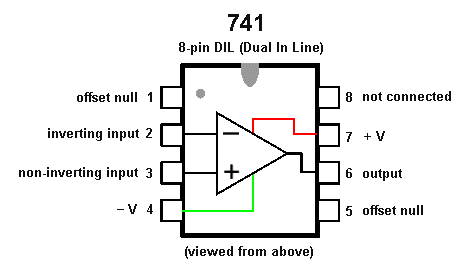
Fig 4: digaram of an operation amplifier. (Note: not all op-amps are wired like this one!)
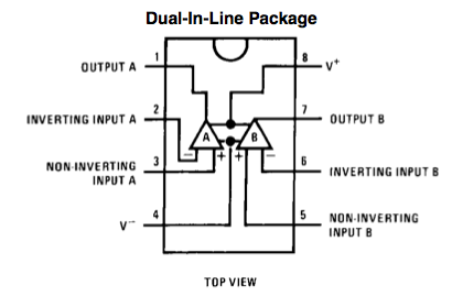
Fig 5: another digaram of an operation amplifier. This one is dual-channel.
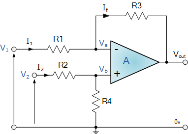
Fig 6: a subtractor circuit (when R1=R2=R3=R4).
|


