A 160M vertical antenna for smaller suburban sites by ralph klimek VK3ZZC Feb 2011 |
| abstract: a
reproducible short vertical antenna for 160m, using a "resonant"
top hat using readily available aluminium stock and
hardware featuring tilt over erection, a base insulator permitting easy
feedpoint matching and total height no exceeding 7 meters.
This antenna is suitable for amatuer construction in a suburban
situation where a larger tower is impractical. |
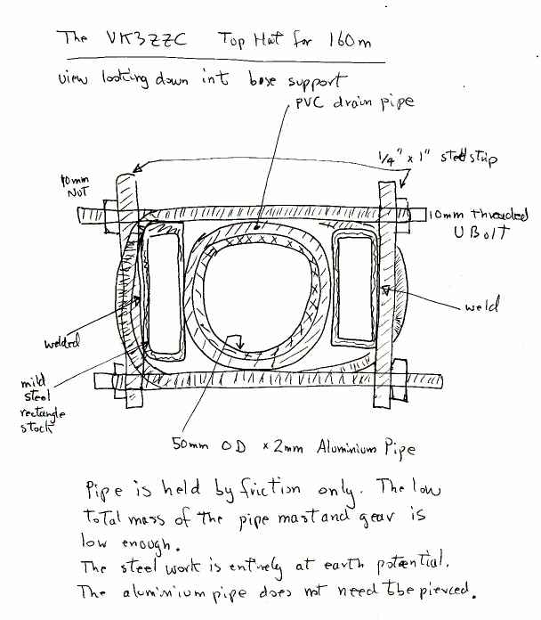
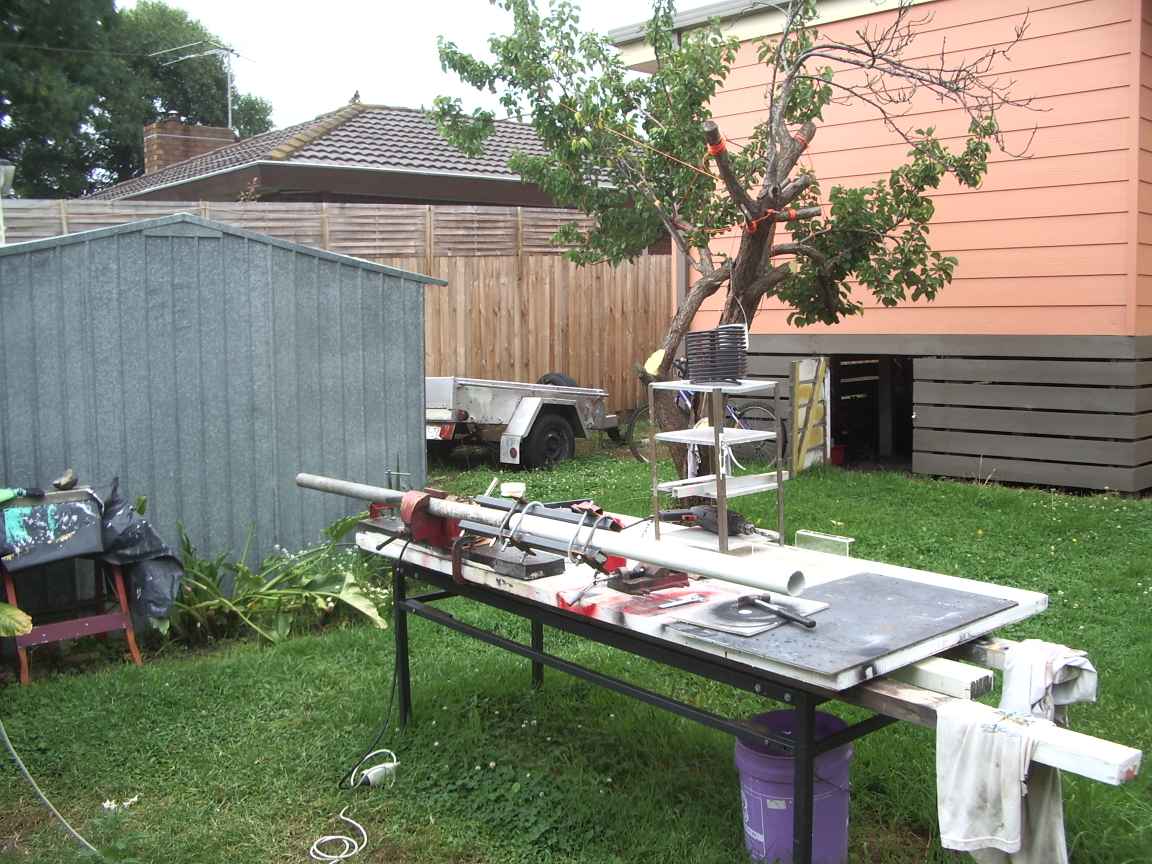
After being most generously given a Seacom Marine AM transceiver by VK3ASE, my attempts to use it were thoroughly thwarted by the simple fact that a horizontal antenna just does not get out, and a short horizontal antenna only 10 meters longs gets out even worse ! Thus was born this project, the aim of which is to to construct a short , practical vertical with an inductively loaded top hat that would be usefull for both 160m and also 80m. It was also meant to be the first practical application of my recent discovery of soldering to aluminium and aluminium brazing. The antenna had to be "self erecting", be self supporting with only minimal guying, be as inconspicuous as possible and also survive being passed of as a flagpole! (for official purposes) It was also rendered possible by the discovery in the industrial waste of some 2 meter lengths of 50mm aluminium pipe. I was initially planning to raise up a 7 meter length of 50 mm galvanized iron pipe. The weight of this meant it could only be raised by a team and would require very secure guying in order to not be a hazard. The 6 meter combined length of the aluminium tube means that I can safely erect this pole without assistance. I can lift the entire assembly with one hand ! There is nothing new in this design, it is all by the book. The variation of the usual theme is that it is base insulated and this caused my many late nights thinking of how I could make a practical base insulator that could also take a high turning moment and be consistant with the need for a tilt over erection mechanism. I think you will find this design to be a practical and readily reproducible. Simulations of short top hat loaded verticals done with mininec showed very high sensitivity of the feed impedance to the top hat dimensions and loading coil inductance. It appears to be so sensitive that actually trying to design something that would present a sensible feed point impedance is nearly impossible. One still must use a bottom loading coil and a low tap to 50 ohm feedpoint. About the only thing I could know for certainty would be the top hat free space capacitance, that at least would permit me to know the inductance of a loading coil. My assumption that assumptions are always wrong lead me to wind the loading coil with many taps so that I could have a choice! Mininec modelling reveals that the bottom feed point would have somewhere between 1000 to 5000 ohms real impedance and a reactive impedance that is critically dependant on the dimensions of the elements and ground characteristics, none of which can be predetermined or controlled. A base loading coil is still required and some means of tuning out an unknown reactance provided. The project was halted, I hope temporarily, by the tail of Cyclone Yasi ( or Cyclone Anthony according to my authoritative source ) which did this to the shack. The pins joining the main tube sections are made from sections of the tubing with a slot cut out. The dimension of the slot is calculated so that the outer diameter of the compressed pin is nearly equal to the inner diameter of the tubing. The ends are kerfed inwards to ease the burden of insertion. It is worth applying a slight smear of grease to facilitate construction. When half the pin is inserted, it is essential to hold it in place with a couple of self tap screws so that the joining operation does not push the pin all the way into the main tube. The ground peg should be cut so that there is at least one meter of penetration into soft ground. I have welded on an ear to permit grounding straps to be attached. I have welded on a hat to the peg. The reason is that it is better to drill the pivot holes on a bench with the required presicion before hammering it into the ground. The hat permits one to hammer the peg without causing severe distortion of the pipe and pivot holes. It also prevents moisture and vermin ingress into the peg. The base mounting, insulates the vertical element and provides a pivot to ease erection and a locking pin below to hold the mast in position. In the absence of wind this arrangement will safely hold the mast up and provide you with enough time to bond the supporting guys. The total antenna mast ,loading coil and top hat can be lifted with one hand. 50mm PVC storm water pipe also forms the top loading coil and double duty as insulator for the top hat. Not really knowing how much inductance to provide, my coil has about 80 turns with a tap every 10 turns. With an capacitance bridge on the top hat, I measured about 55pF free space capacitance near ground level, so the 100uH, as measured, coil should work out fine. It is actually possible to work out from first principles the free space capacitance of the top hat and add a fudge factor. Maybe this may yeild a more accurate result then the capacitance bridge which gave a very indistinct null.6 The U Bolts were made from 10mm metric threaded stock and bent on a purpose biult mandrel. The U bolt saddles were made by cutting U section aluminium extrusion with a circle saw. The secret in cutting a partial circle with a circle saw is you must provide a stable pivot for the circle saw. All these needs is a entended pilot drill shaft in the saw arbour which projects downwards into a wood block with a nice perpendicular predrilled hole to take the pilot with minimum slack. The workpiece is screwed securely to the wood block. Perfect arcs can be cut in irregular material this way. I still need to think about nice way of mounting the base loading coil. Here is the problem. The mininec simulation shows extreme variation in the base feed point reactance. So where should I put the top hat resonance; top, end or middle of band ? If the reactance is net capacitive I then do not need to provide a variable capacitor at the base and can tune it out with the right loading coil tap. I cannot trully model this antenna because I cannot account for my counterpoise of assorted wires and tin sheds and variable conductance ground. The poor ground conductance will broaden the resonance curves and nearby trees make the near field unpredictable. Other things to think about. My primary motive is to get on to 160m. Could the completed antenna also be suitable for 80m ? There is nothing special about the size of my elements, no matter what they are the WRONG size by afactor of TEN ! An 80m vertical would only need a differant top hat inductor. I have not yet made provision for a means of remotely shorting out unwanted turns to make the top hat work at 80m...this may happen further down the track. If the coil were totally removed it would make a respectible 40M short vertical. The mast when complete will also be fitted with a halyard so that a flag can be displayed, thus dispelling any question ,whatsover, what the true purpose of this strange contraption actually is ! Many thanks to Nigel, VK3DZ for helping me put it up for the first time the other day. Still to do. More guys, (done!) maybe I am just paranoid but it cannot hurt. I have run a control wire up the inside of the main pipe. One day this will control a relay box at the top hat coil to short out turns to permit operation at both 80 and 40 meters. I still need a good way of doing RF isolation at the base to power the relays. This is not a simple problem because the base feedpoint impedance is huge and significant RF voltage is present. The capacitance of the base insulator is about 50pF, mostly insignificant at 160m but could be annoying at 40 meters. After two years in the air a couple of things have happened. The guy ropes had decayed in the fierce Australian sun and after thousands of milli-Pidgeons top loaded the top hat elements and bent them nicely downwards, rendering them useless. Once again Nigel, VK3DZ lent a hand and the mast was lowered, new guys installed and a nice new halyard was installed so I could fly the new happy-and-glorious and once again reclaim all the territory of Oz for King George III. The old flag had flapped itself to tatters . The old guy ropes were very dangerous. We are sold very cheap but very nice looking "poly propylene" rope. It has a nicely woven outer braid and an inner strenght member that it made from spun lolly paper and nappy liner material ! Do not use this so-called rope in any outdoor critical application , especially for guy ropes. After two years the inner member could be broken with simple hand pressure. I replaced the topmost dust cap with a plate to which aluminium mig wire is attached and this now guys the top hat elements. The birds now happily roost on this loverly perch without causing me pain. I live nereby a wetlands conservation area and large waterfowl have found another use for my antenna...er, um..flagpole. For guys, I am now using a very tough poly propylene blue and yellow linesmans draw line rope. This is abundant, cheap, weather proof , amazingly tough and can be purchased new in 250 meter drums or is often discarded by Telco linesmen after a cable pull, as they are not permitted to re use it after a cable pull. I can attest to the positive PR value to Amatuer Radio operators in hoisting a flag on your pride and joy radio mast. My neighbours have all complemented me for my evident patriotism, I very much doubt they would have praised the antenna. |
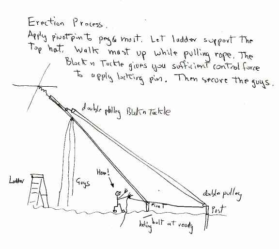
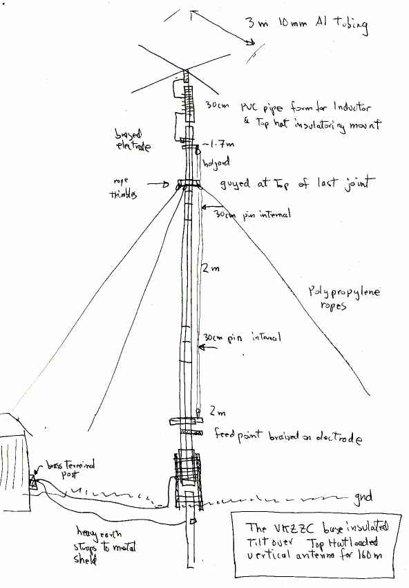
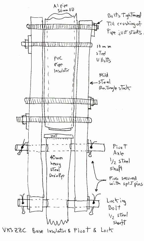
| what i wanted to biuld, the cunning plans ! | |||
 |  |  |  |
| how to put it up | general detail | detail of tilt over pivot and insulator | plan view of base insulator and structure |
| and look what I got ! | ||
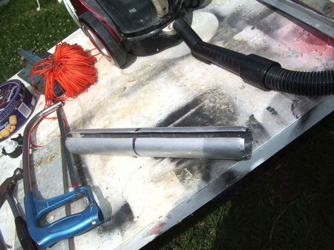 | 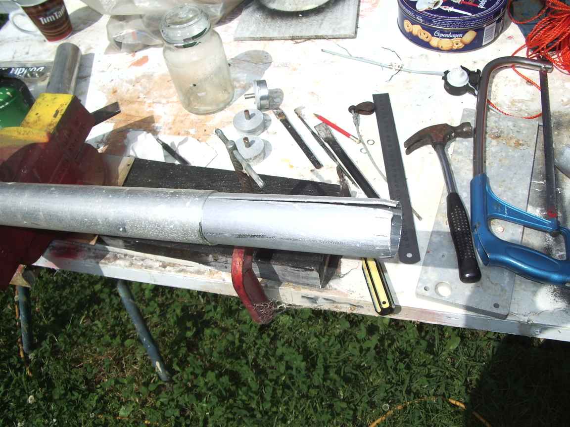 | 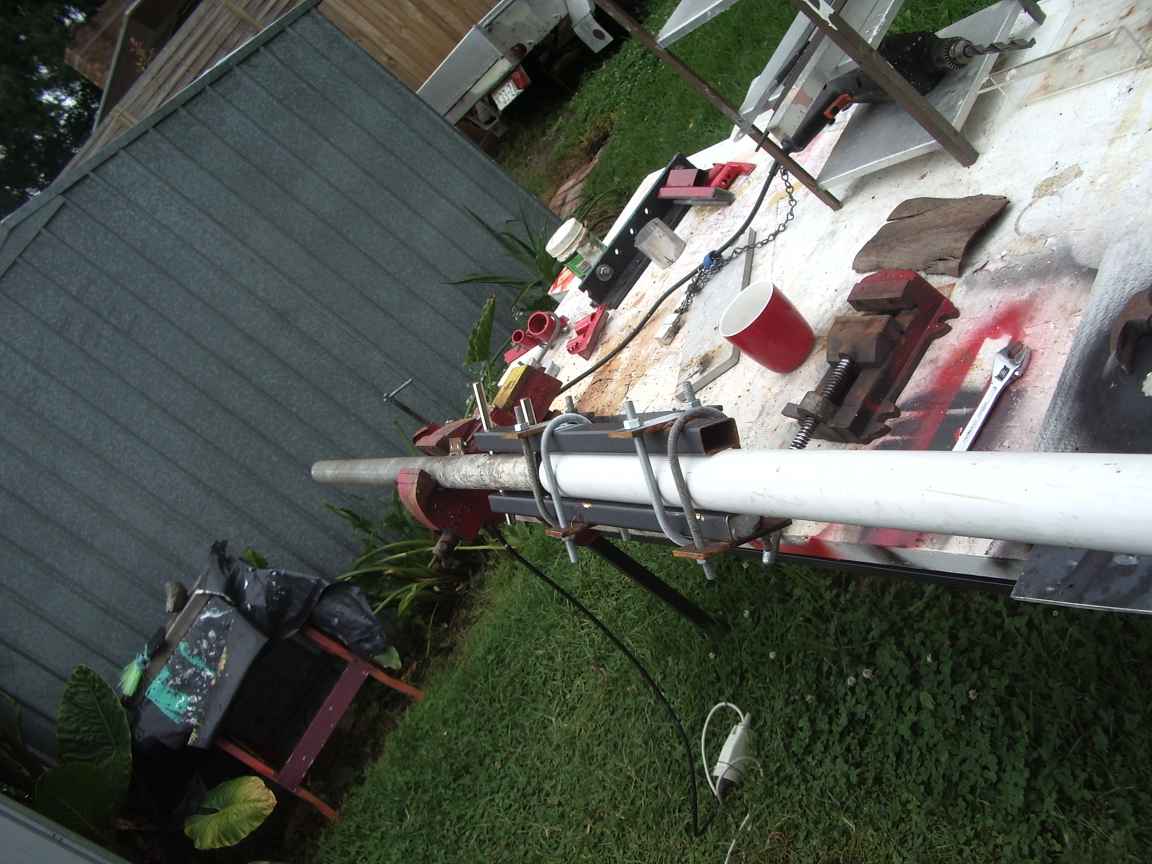 |
| a pin for joining 50mm Al pipe. I cut the slot with just an angle grinder. | a pin for joining 50mm Al pipe inserted halfway into a section of 50mm pipe | completed assembly of base, pivot , base insulator. PVC drainpipe fits nicely over 50mm tubing. |
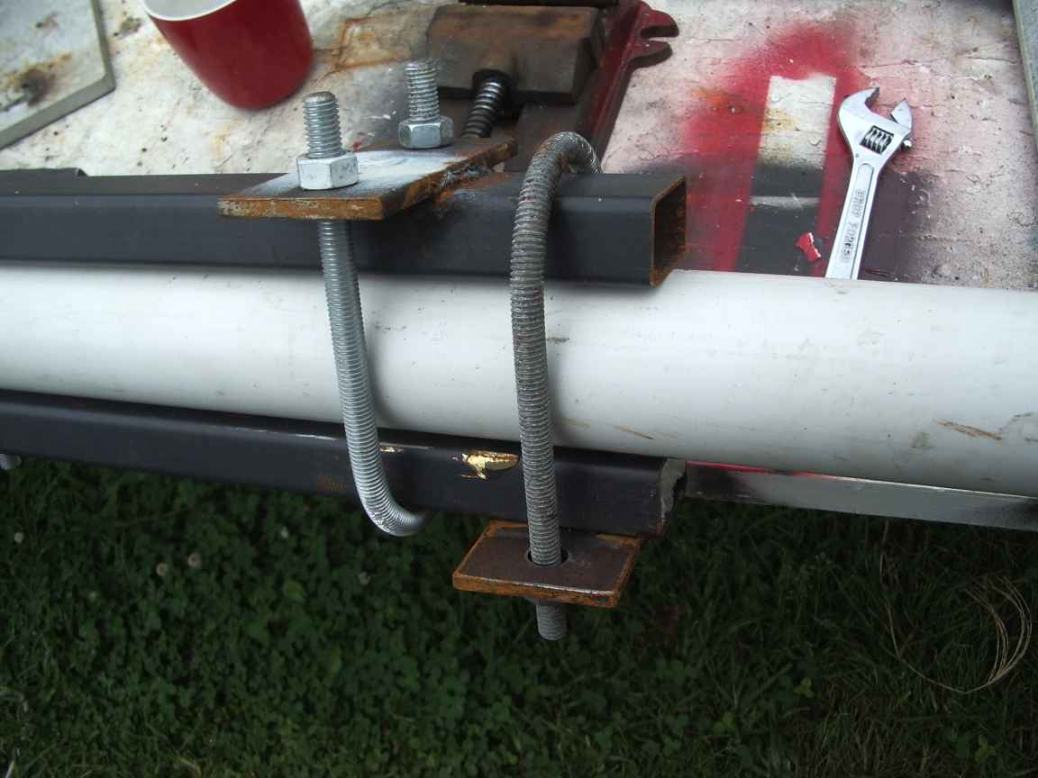 | 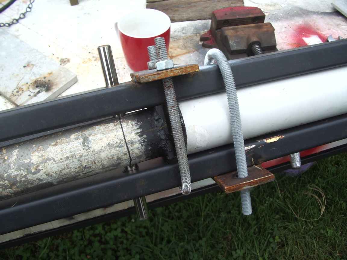 | 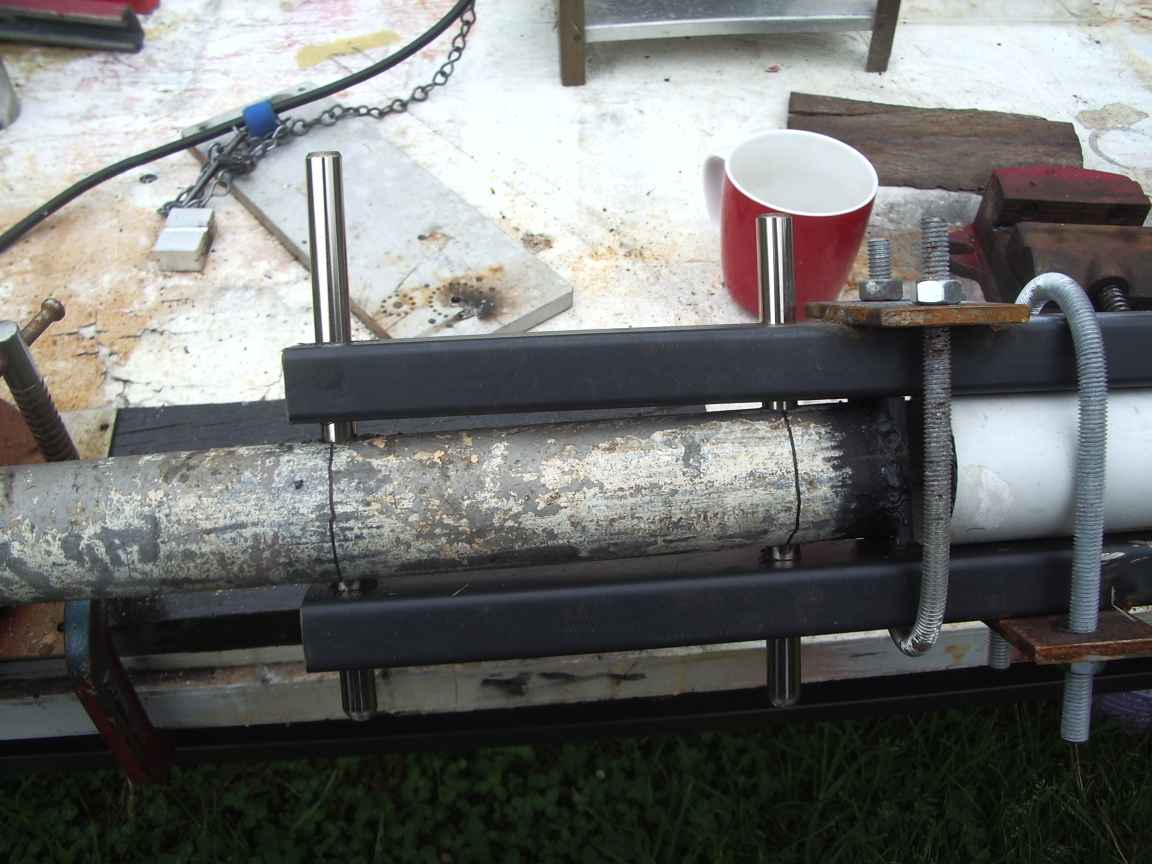 |
| holding onto the base insulator.The U Bolts were made with this Bender | ground peg and pivot pin and base insulator | ground peg and pivot pin and base insulator and shoot-bolt to secure the pole |
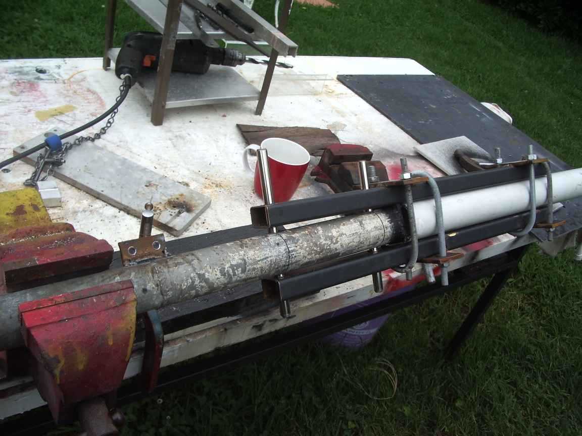 |  | 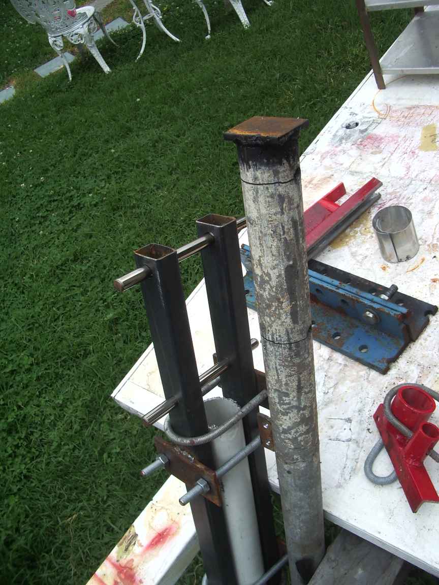 |
| ground peg and pivot pin and base insulator and locking pin to secure the mast , vertically. | ground peg and pivot pin and base insulator under constructio | the ground peg is a length of 2inch galvanised heavy drainpipe. It is fitted with a welded on hat to facilitate hammering into the ground without damaging the predrilled pivot holes. |
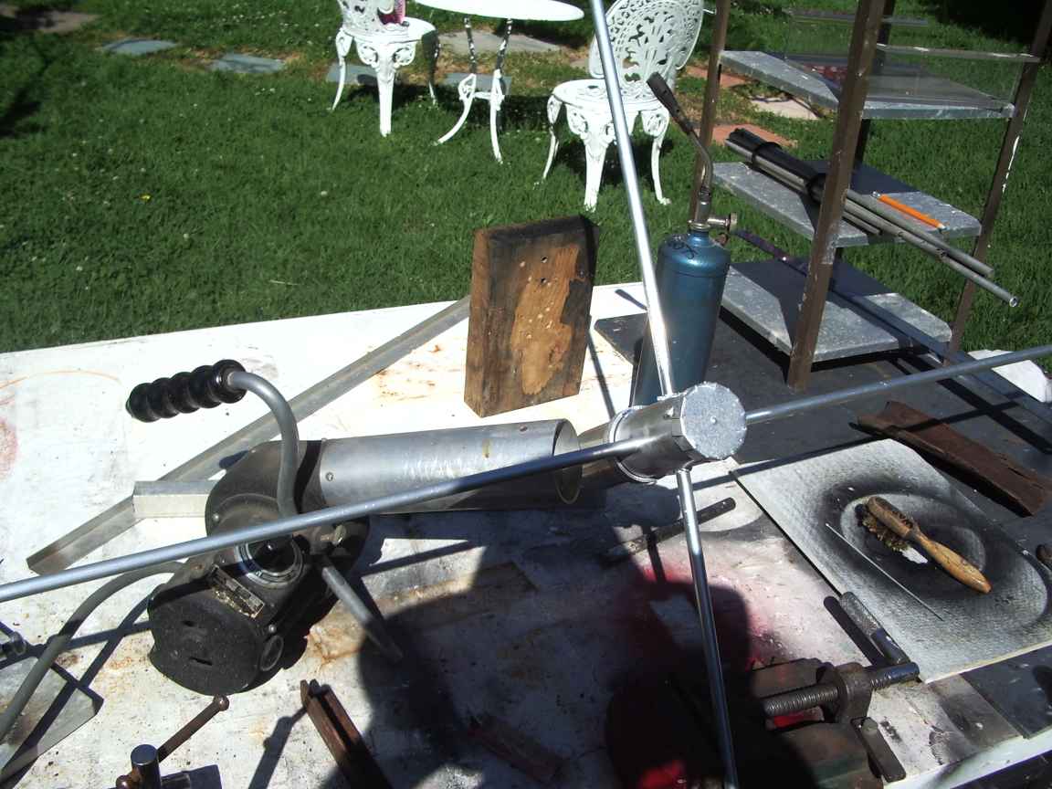 | 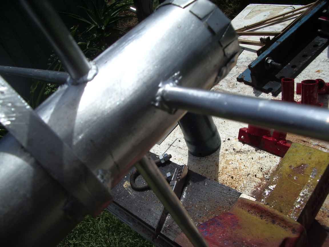 | 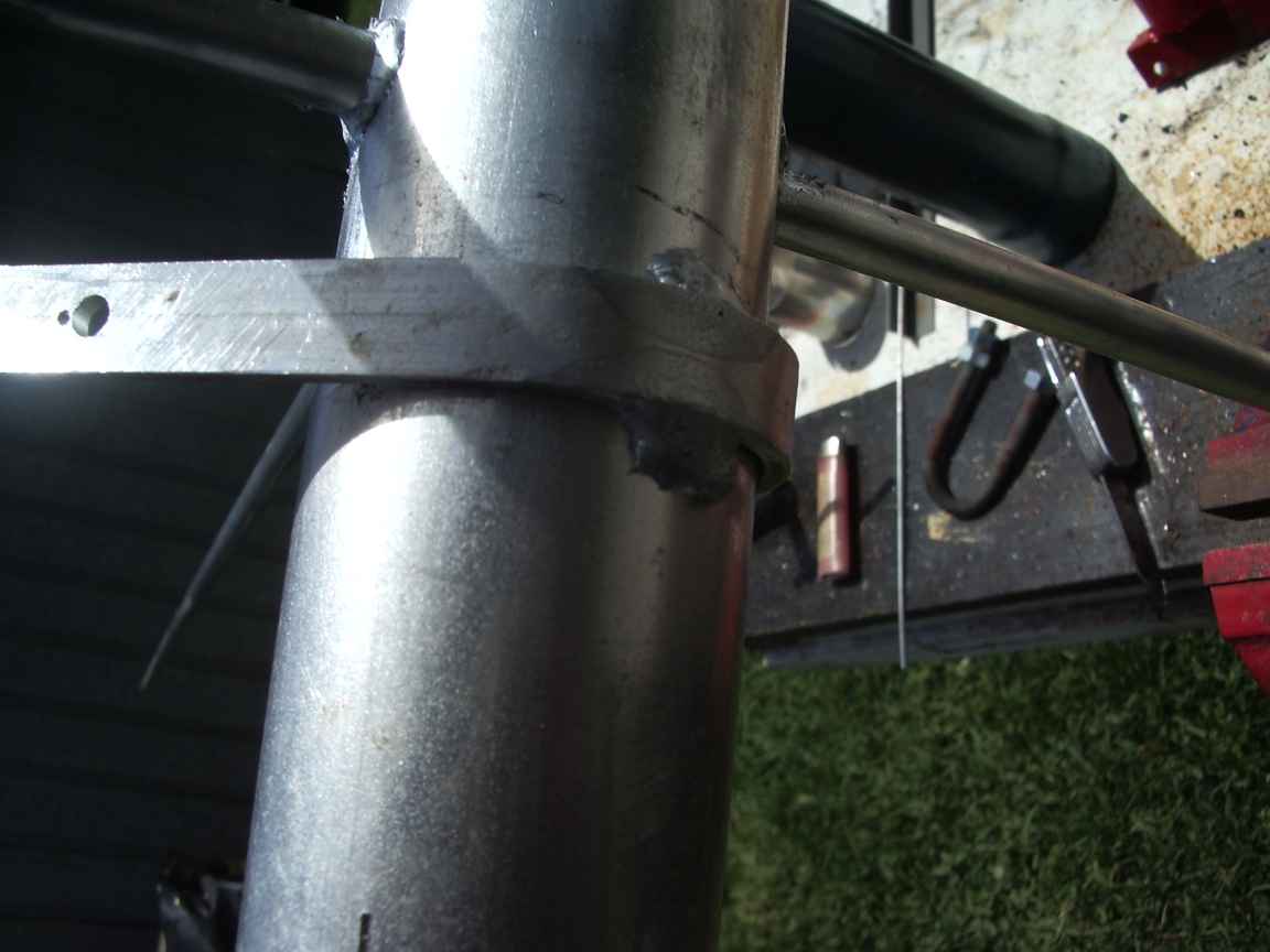 |
| the top hat being brazed. The heat gun provides supplemental heat | top hat central joints are brazed, nice job The top hat also has a hat to stop water and vermin ingress. | the electrode brazed to the top hat assembly |
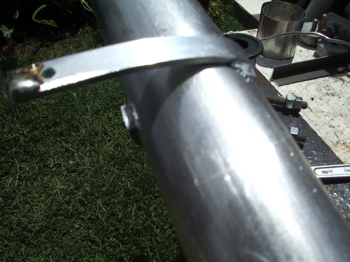 | 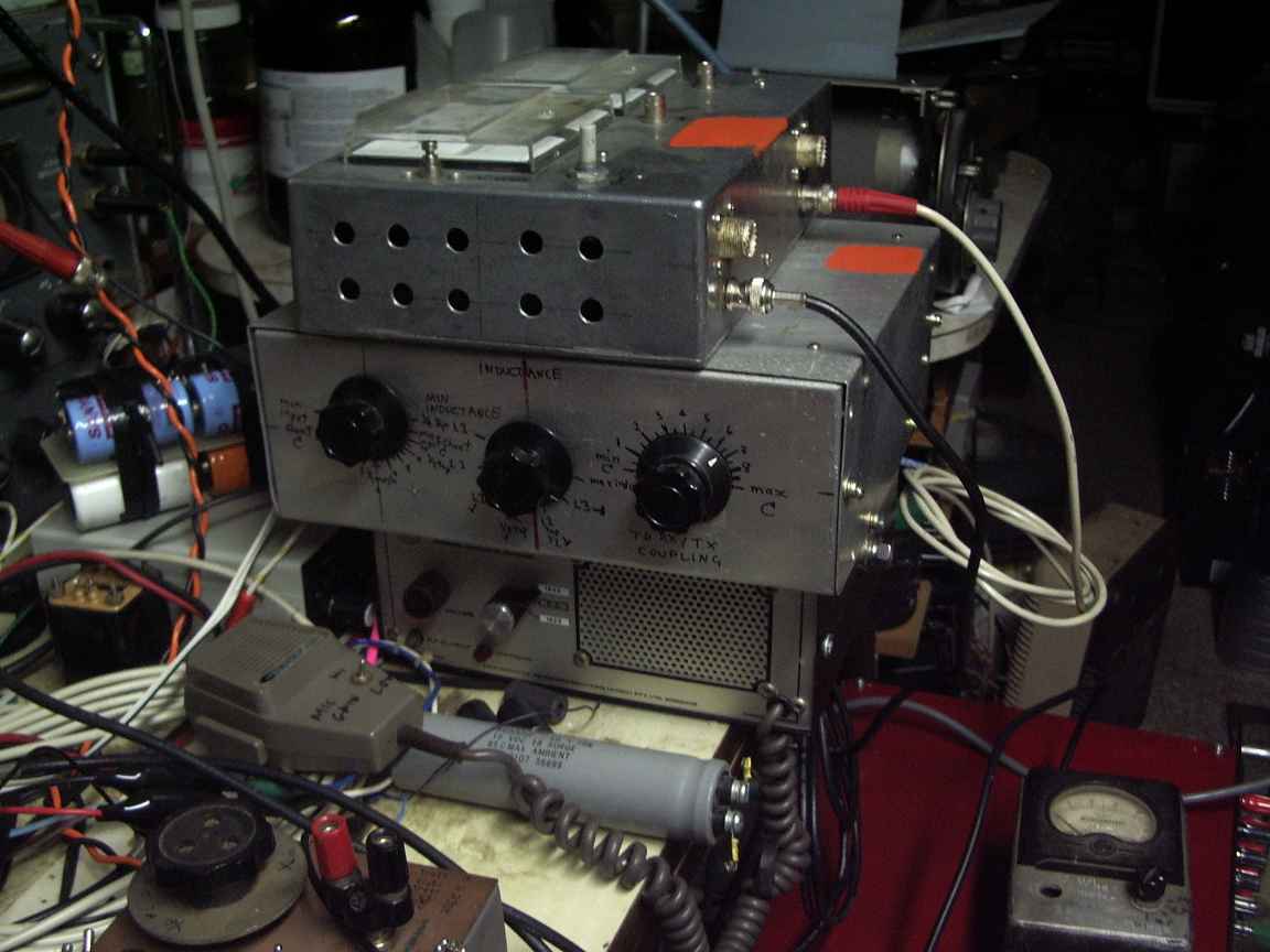 | 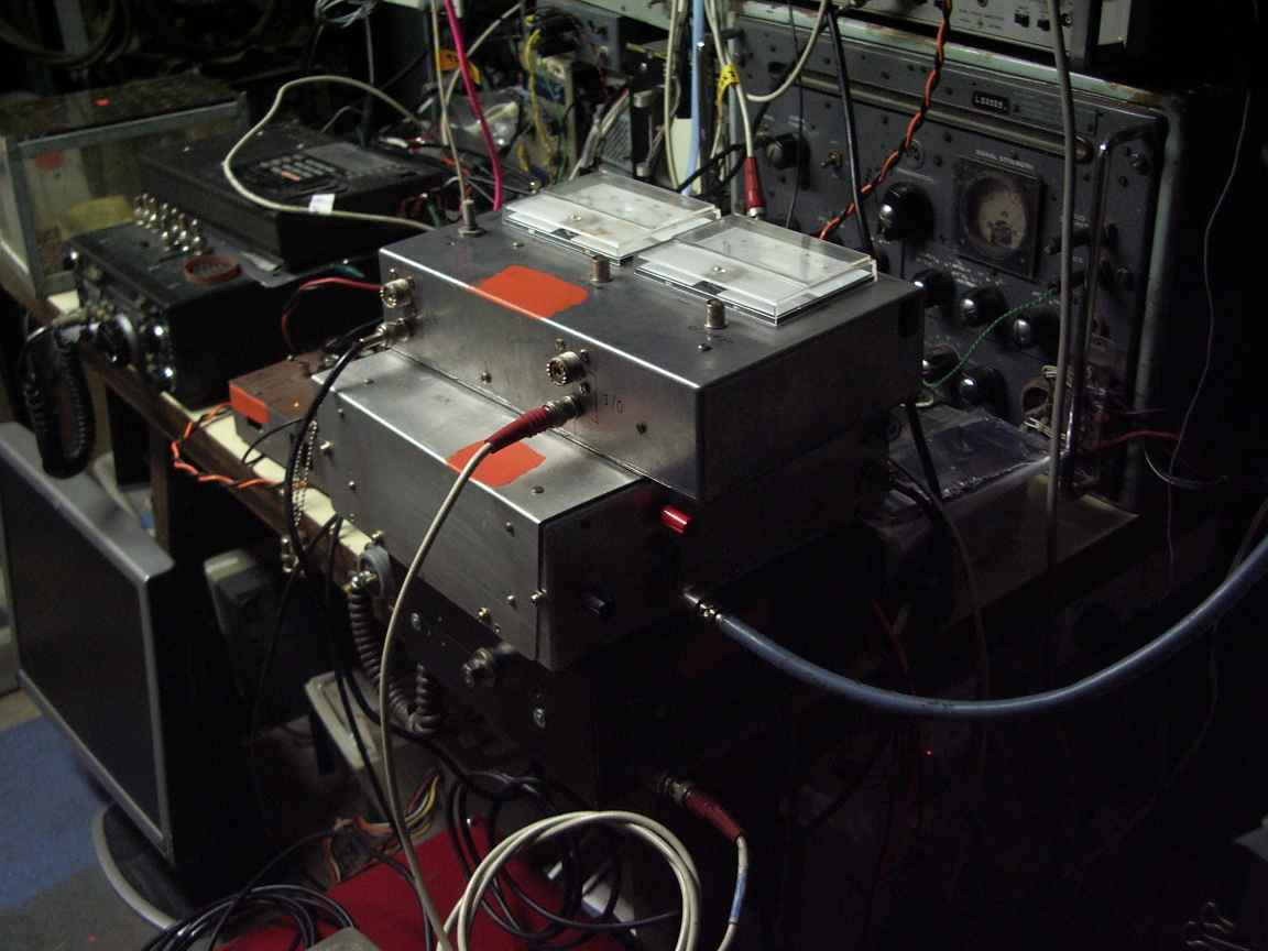 |
the electrode brazed to the top hat assembly. Notice the solder blob on the aluminium electrode. How did I do that,eh ? | Seacom 40 with ATU and reflectometer We get about 5Watts carrier out. | Seacom 40 with ATU and reflectometer the A618 in the background is the main shack radio, still after 50 years ! It is the main RX for 160m. Valve front end gives me EMP and burnout protection. |
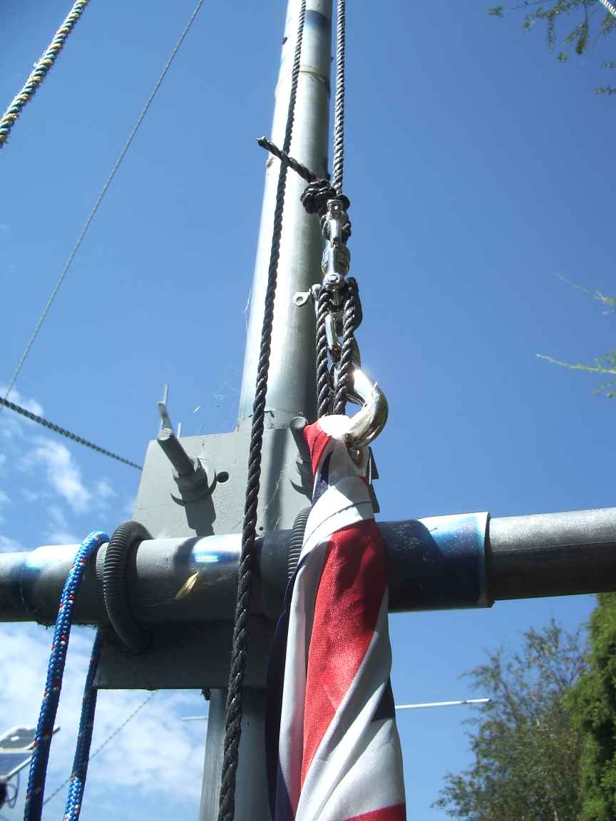 | along
here is the halyard mount and temporary coax feed. The
counterpoise consists of one 6 meter long, 3meter wide metal radio shack and some
earth wires. on the left is the new halyard for the "happy-and-glorious" . a flag halyard over time begins to develop a serious amount of twist that renders hoisting a flag impossible. Use a universal swivel to relieve this twist. I do not know how the twist accumulates | |
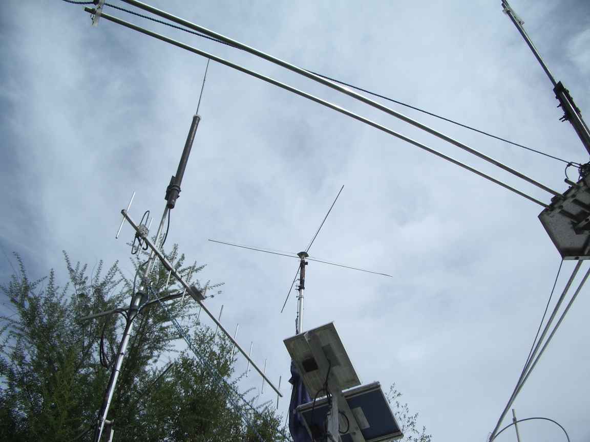 |  |  |
| above: new top hat assembly, elements are now guyed to prevent bird damage | ||
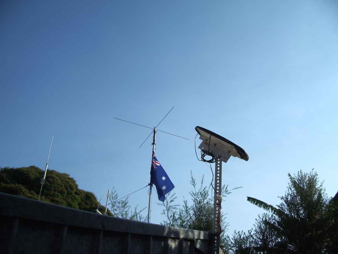
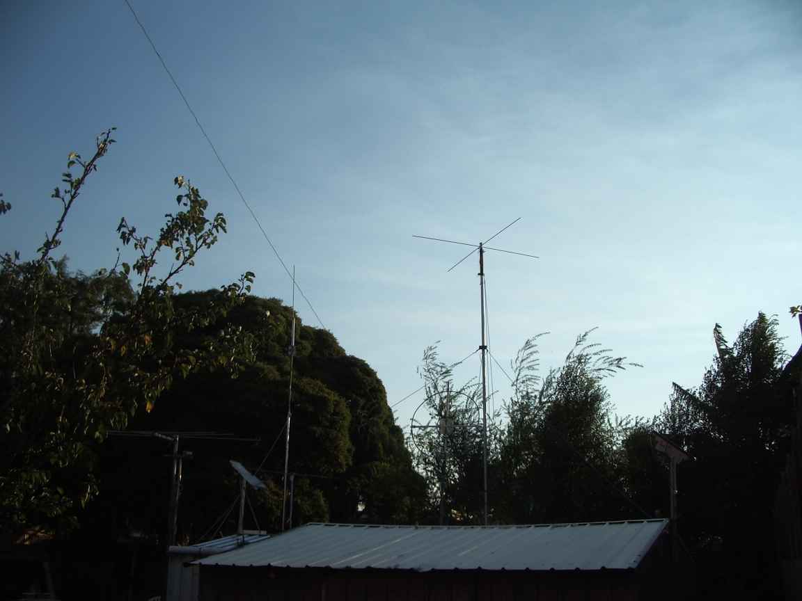
the original un guyed top hat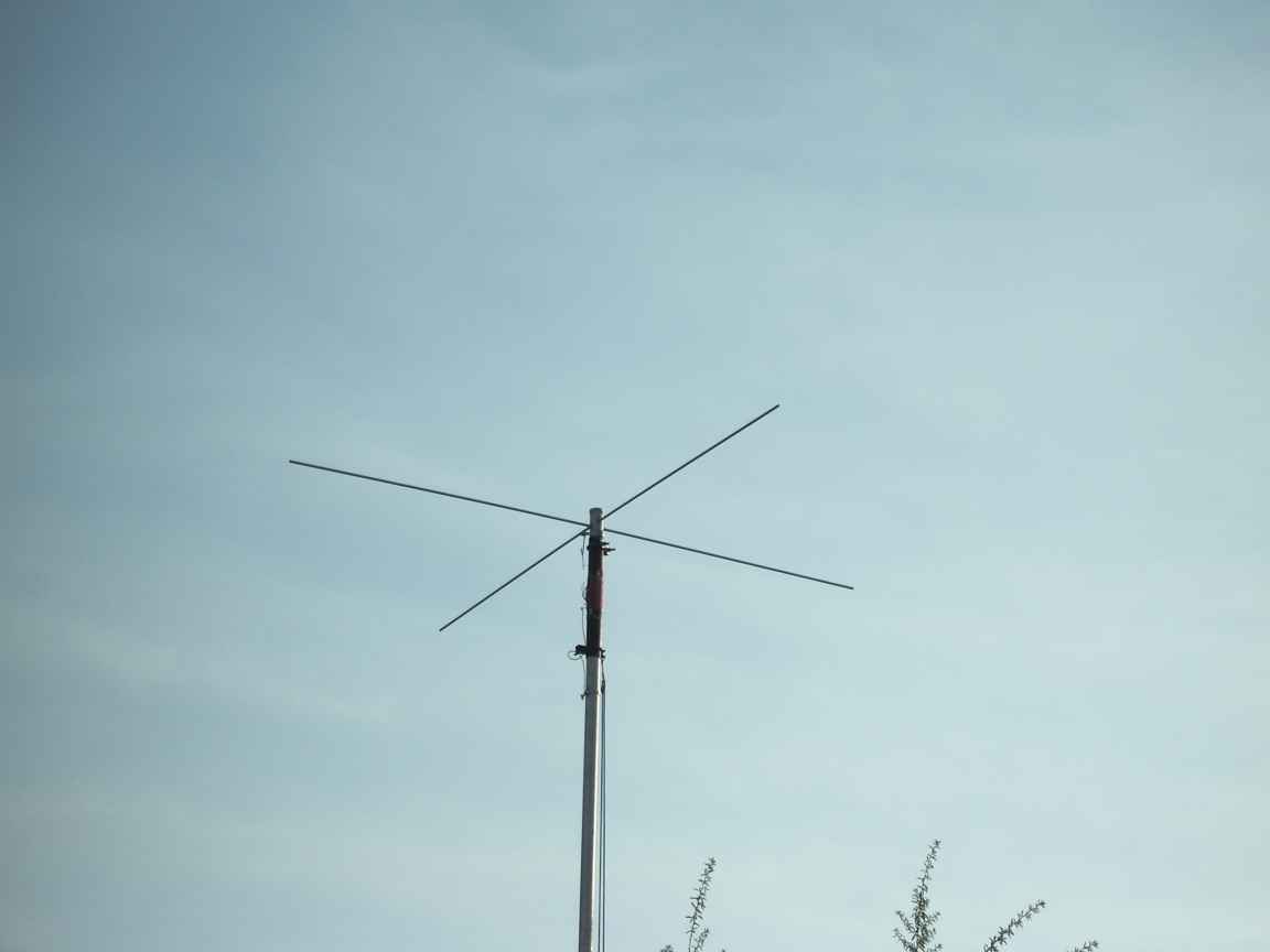 | the "happy-and-glorious" ...rampant !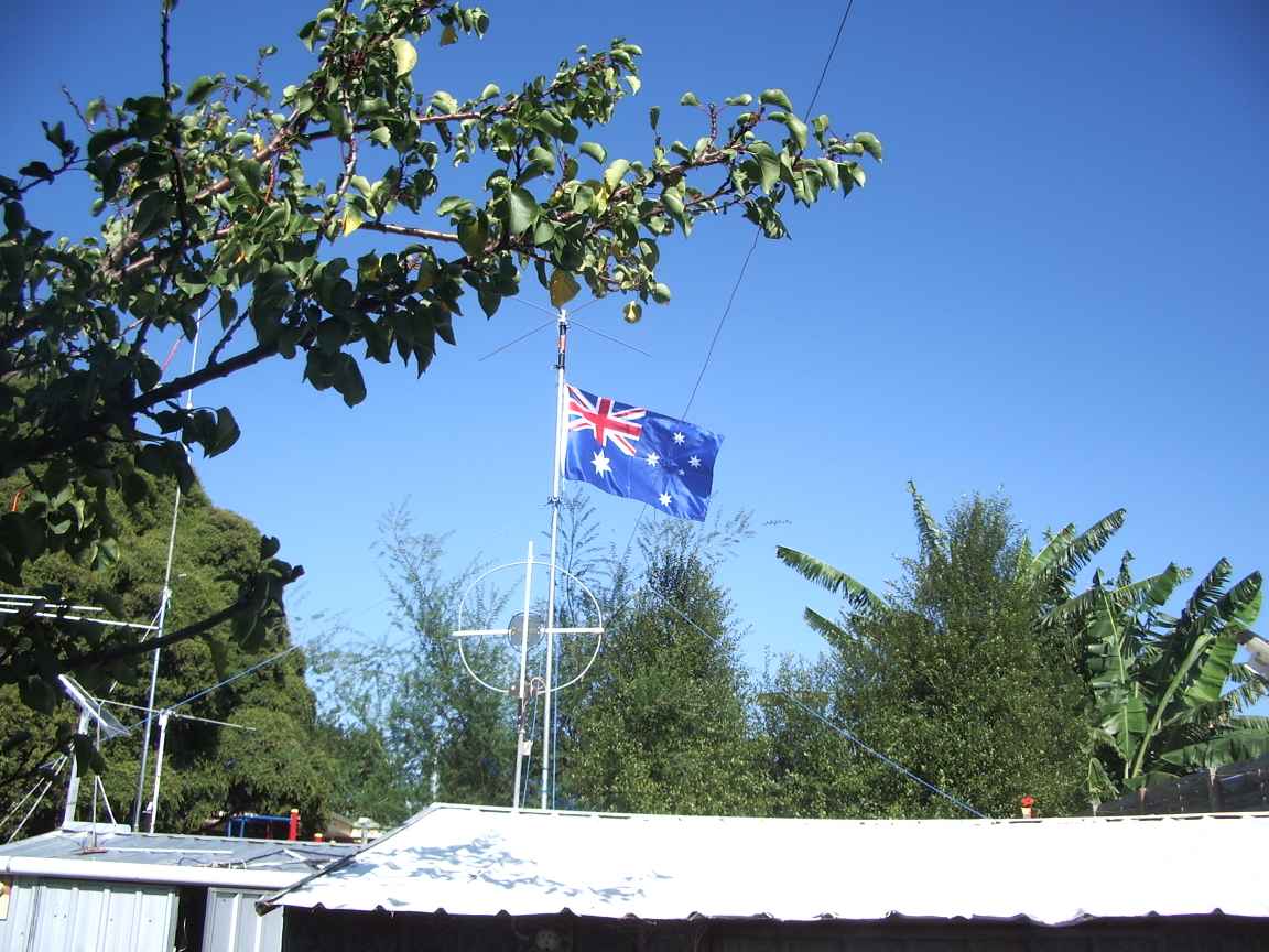 | 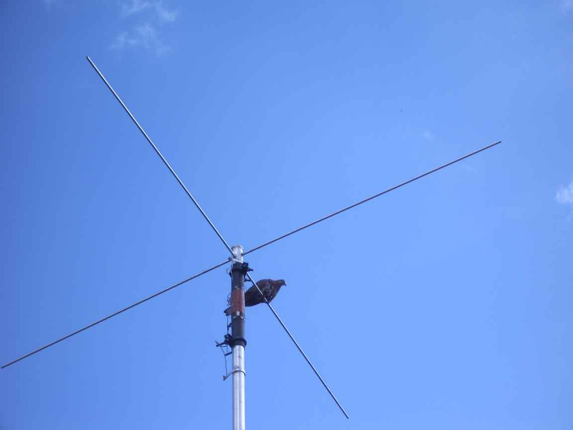 The top hat should be loaded with 1000 milliPidgeons for best results |
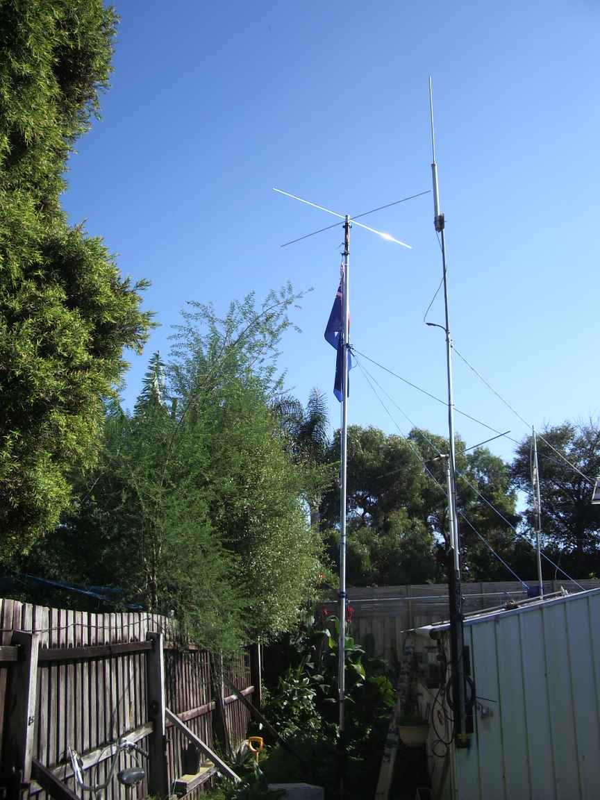 | 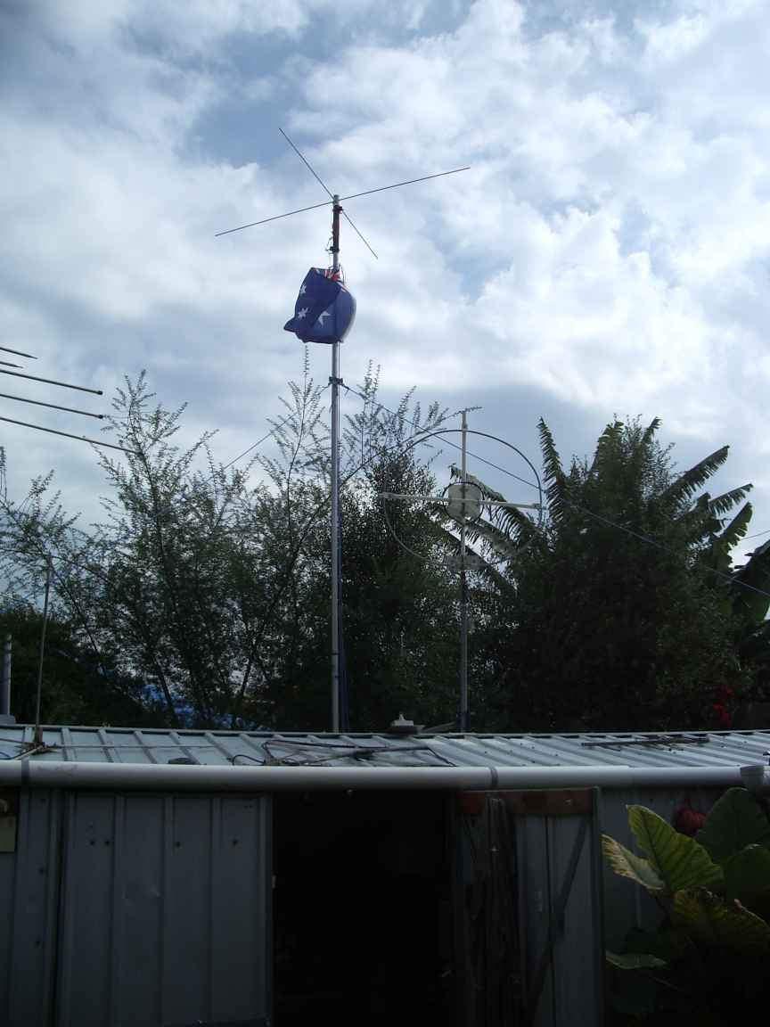 | 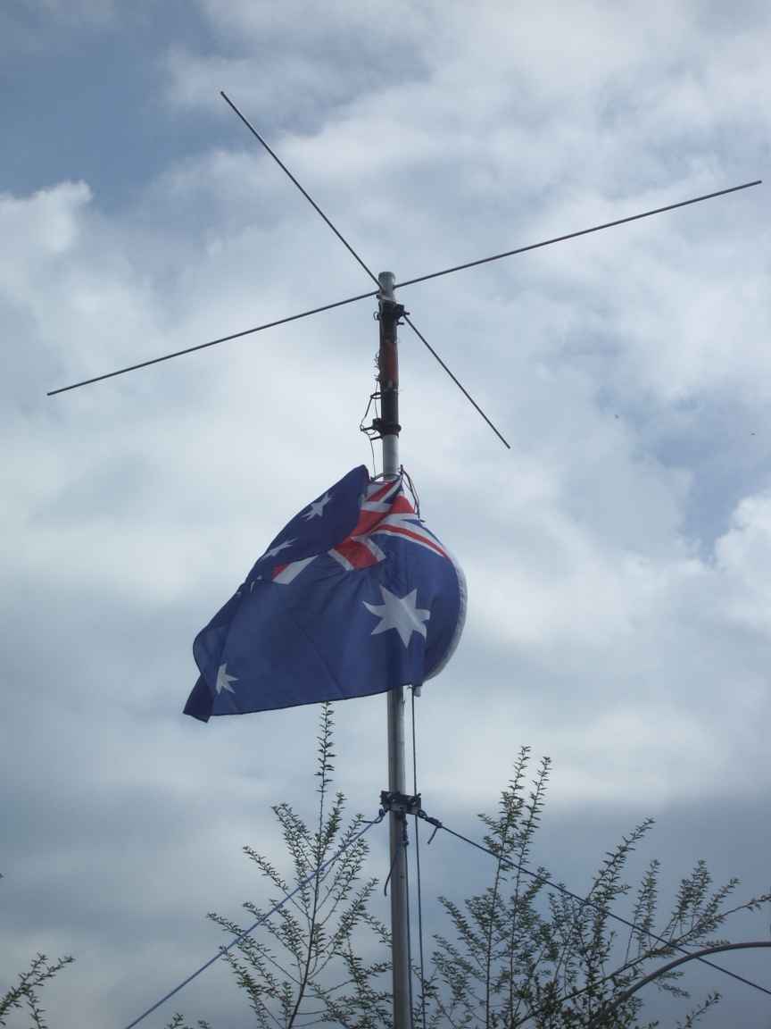 |
| it joins a pipe holding the 2M J-Pole and general purpose vertical (lousy) radiator | 160m joins the antenna farm. The shielded loop drives the Rx | view of loading coil and top hat |
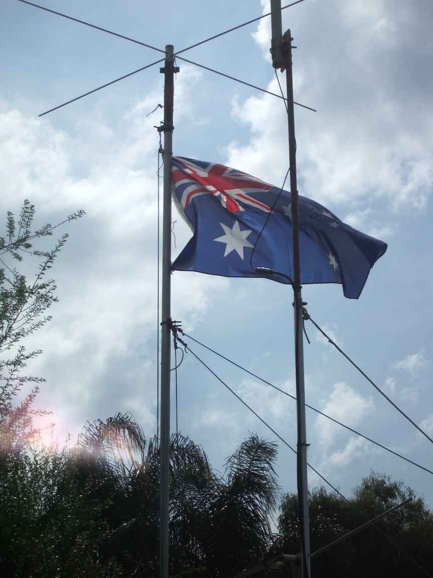 | 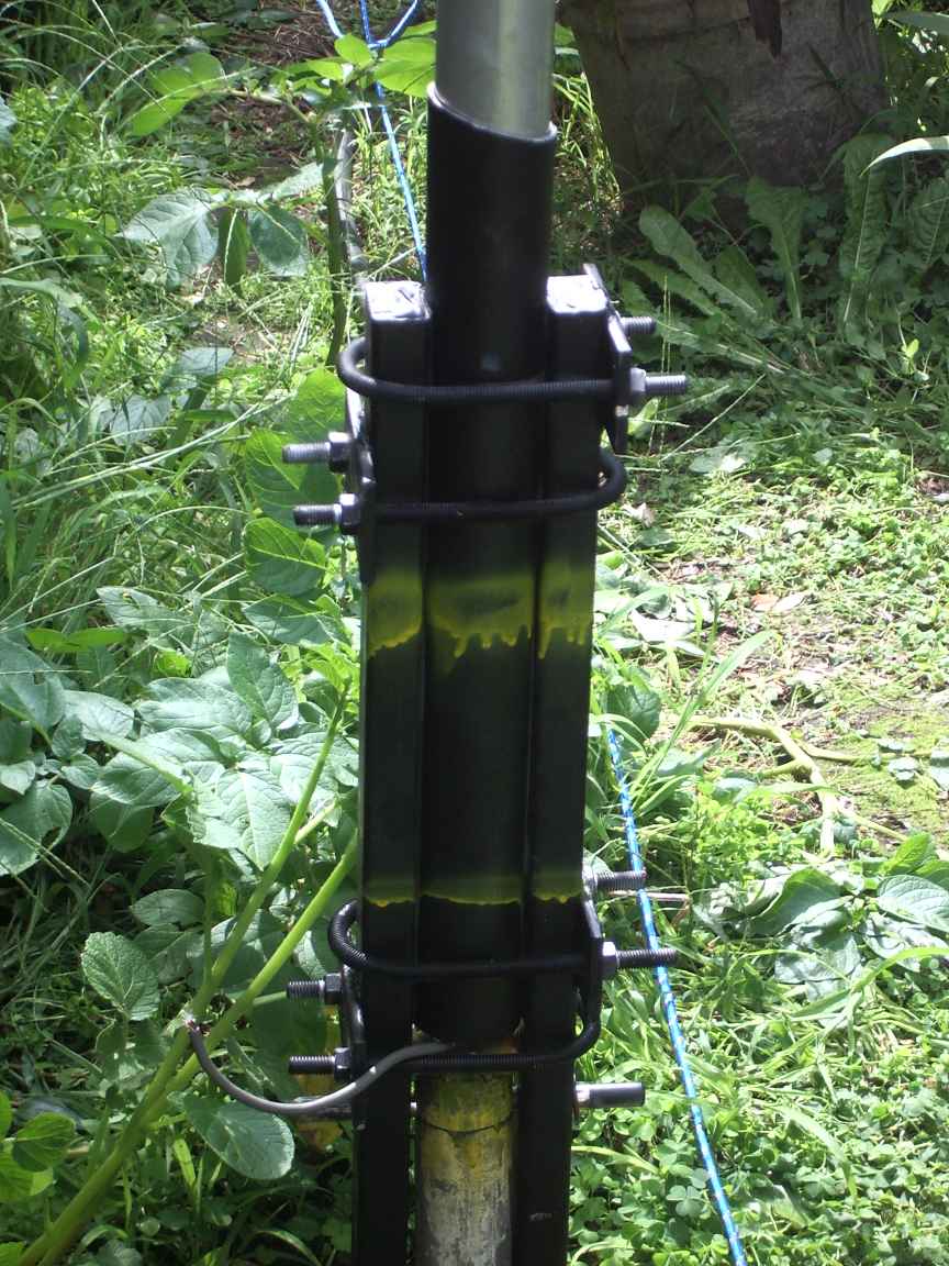 | 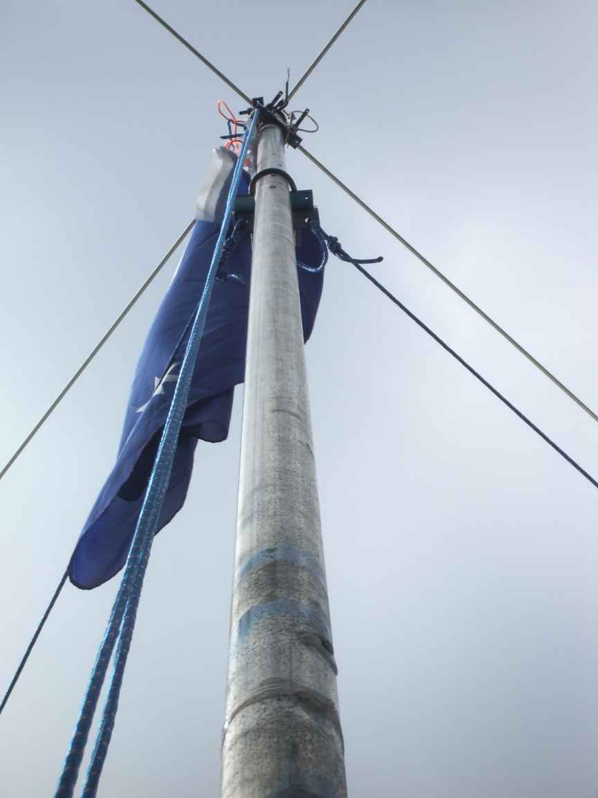 |
| God save the King ! | base insulator, pivots and locking pins The locking pins are drilled at the end to permit the pins to be secured in place with split pins, as the winds rocking motion can cause the pins to displace. | halyard |
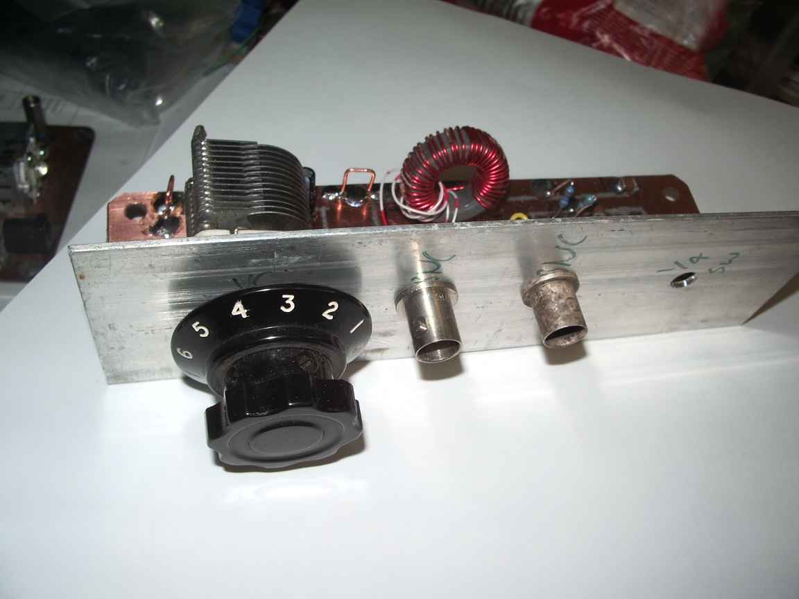 | 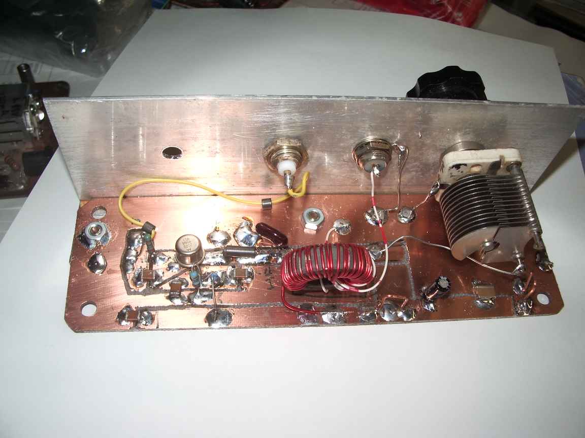 | 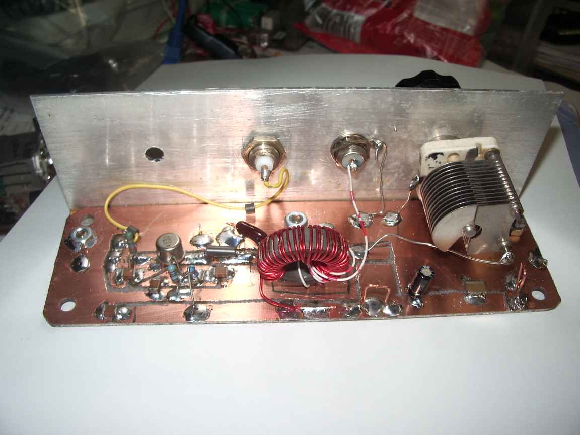 |
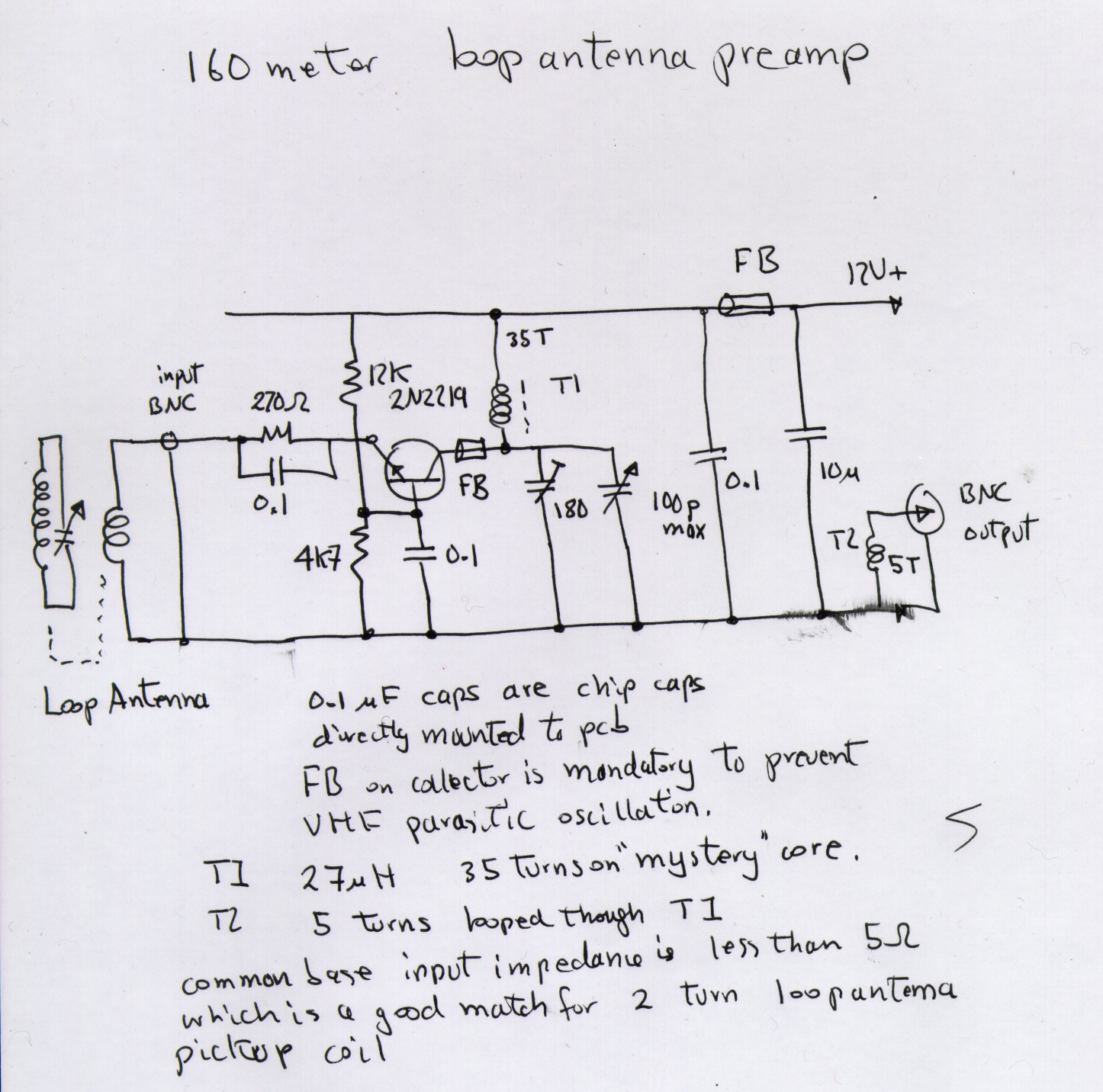
| Pre-amp for 160m loop antenna | ||
 | ||
 |  |
 | 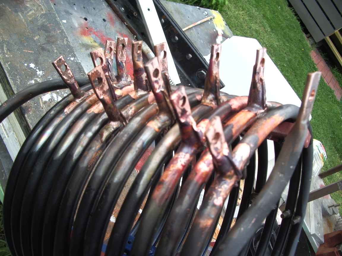 |
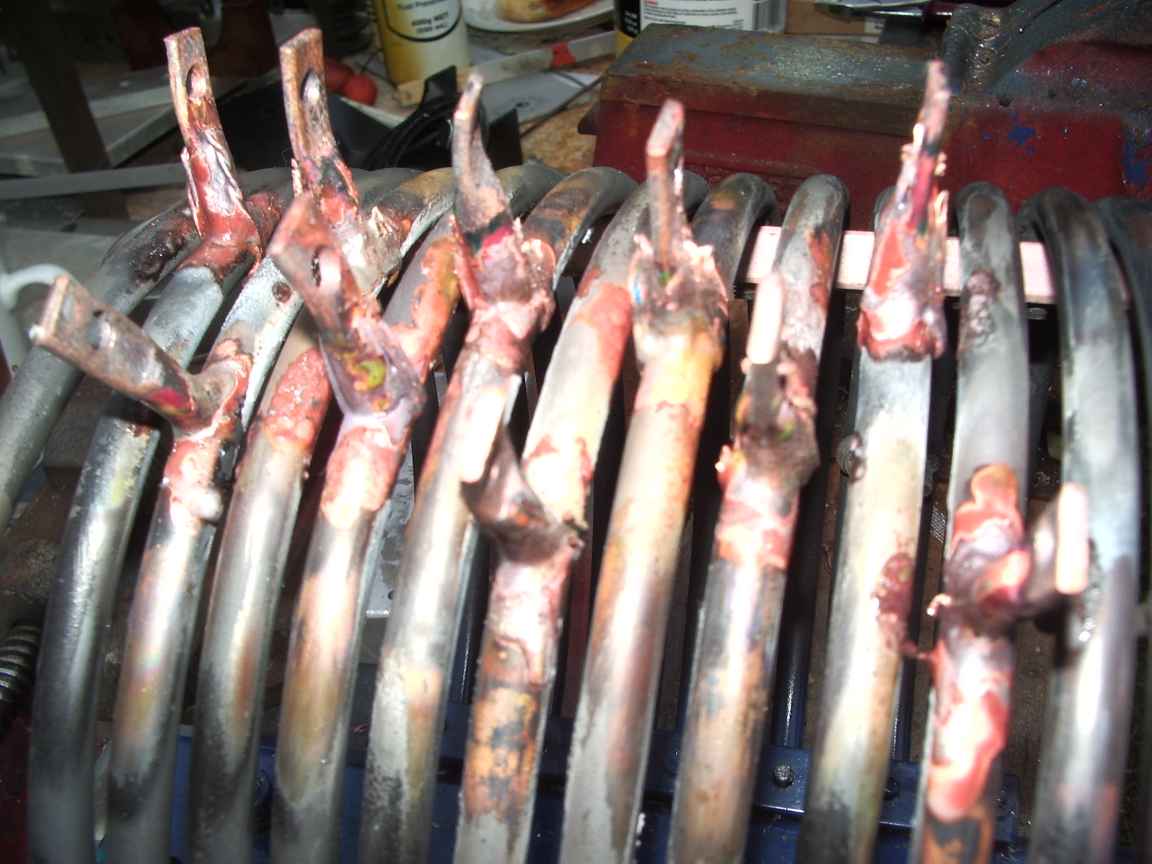
| the lugs are pre made from copper pipe. You can still see where steel wire has been used to secure the lug during brazing | |
 |  |
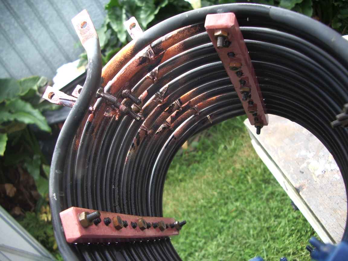
| the coil-o-doom mounted at the base insulator. the box contains a tuning capacitor. The whole antenna with top hat, according to my noise bridge resonates at 6.00Mhz and also at 1.9Mhz due to the series top hat inductor and self capacitance of the top hat. Matching this to other ham bands is a challenge. The transmatch gives a good match to 160M, 80M,40M (sorta!) and 20M. Higher bands wont work, I expect that is due to the top hat. Still to be done, a relay box up the top inductor to short out the loading coil for higher bands. This is hard to do due to having a "hot" insulated base mount. | |
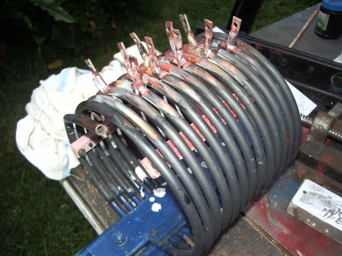
What is this ? This is the new base loading coil made for the 160M vertical.It
is made from 5/16 diameter hydraulic copper pipe. The coil was some
sort of heat exchanger I recovered from the Engineering dumpster and
have repurposed to serve as a coil. It started life as a coil, it
is just more "coilly". The industrial strength taps on this coil
were added by me. There is no particular purpose for these taps ,
apart from increasing the utility of this coil for antenna
loading. It was a bit useless without the taps as it would have
been quite hard to find and then attach a feed point wire. The real
purpose of the taps was that I had purchased a Bernzomatic Fat Boy
Propylene burner so that I could learn how to braze copper and other
things. This project provided a platform with which I could
acquire this skill and practice it. It worked quite well and I am
most impressed with the Bernzomatic Burner. Propylene does not
burn as hot as MAPP. I had originally wanted to buy a MAPP gas burner
but these are sadly no longer made as the last commercial producer of
MAPP gas has ceased operations. MAPP was the "poor man's
acetylene". I would like the utility of acetylene, however there
are some very significant cost, safety and licencing hurdles to
overcome, for which I do not have the will or need. Propylene
will have to do. It is good enough for silver bearing
brazes but still is not hot enough for a true Brass/Steel brazing
operation. The Bronze brazing rods sold with the Bernzomatic
torch have a low enough working temperature to be used for steel and
iron brazing with this propylene torch. It is a real shame that MAPP gas is no longer available. Brazing
is not like soldering. Once the brazed
joint is formed it cannot be "reflowed" as in soldering. If a
mistake is made it must be ground away and you begin again. The
reason it cannot be reflowed is that the silver which forms a eutectic
in the braze is absorbed into the the copper base metal. The melting
point of the the braze filler metal is now too high to reflow, thus,
you only get one go to get it right. The molten braze has
an extremely high surface tension and provided that the base metals are
clean and fluxed, the molten braze will readily penetrate and fill
gaps. The bond that forms is extremely strong and weather proof,
unlike joints made with traditional lead/tin alloys. The tap elements
were formed from copper pipe and held in place with copper wire for the
brazing operation. There is no "third-hand jiggery pokery"
that works for simple soldering, brazed elements must have
positive support during the operation or they will move about. The flux paste is based on potassium hydrogen flouride and boric acid. The fumes are extremely irritating and mildly toxic, so this is strictly an outdoor operation. The flux residue forms an interesting blue glass which quickly absorbs moisture and goes green and tacky. It can be removed with a water jet. ~ | |

