Mon Sep 26 18:10:06 EST 2016 Thu
Feb 9 18:28:54 EST 2017 added 6M atu

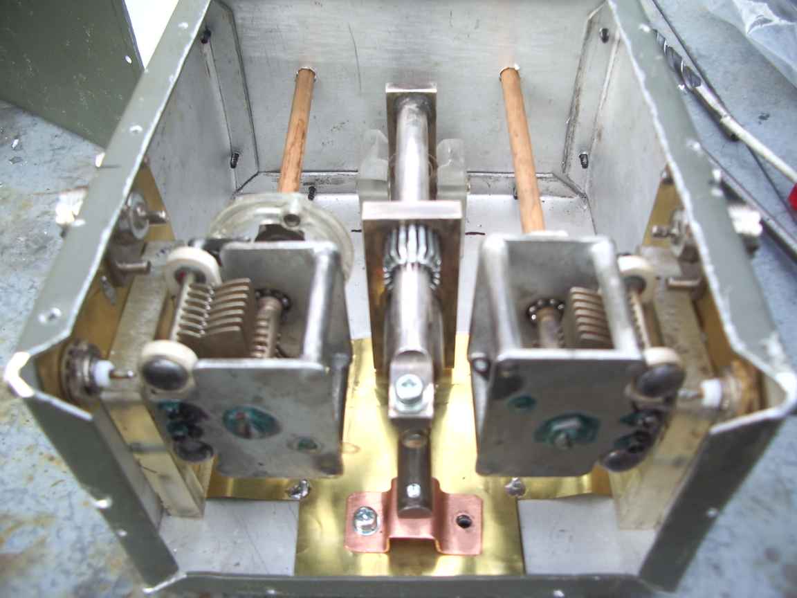
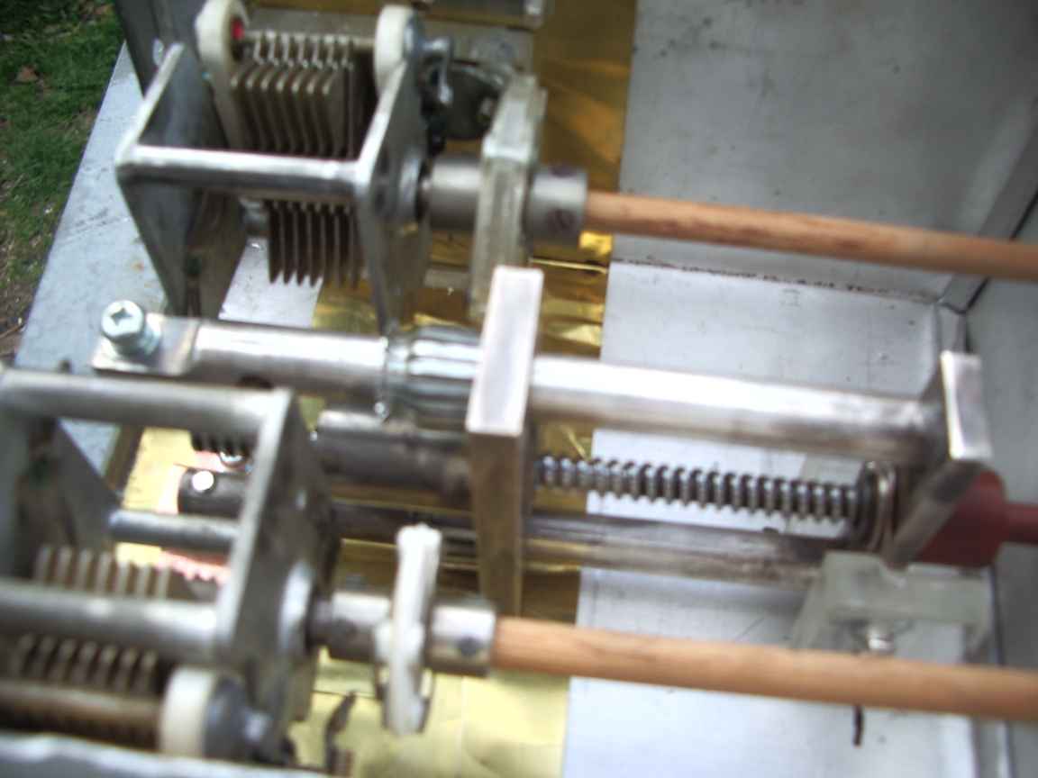
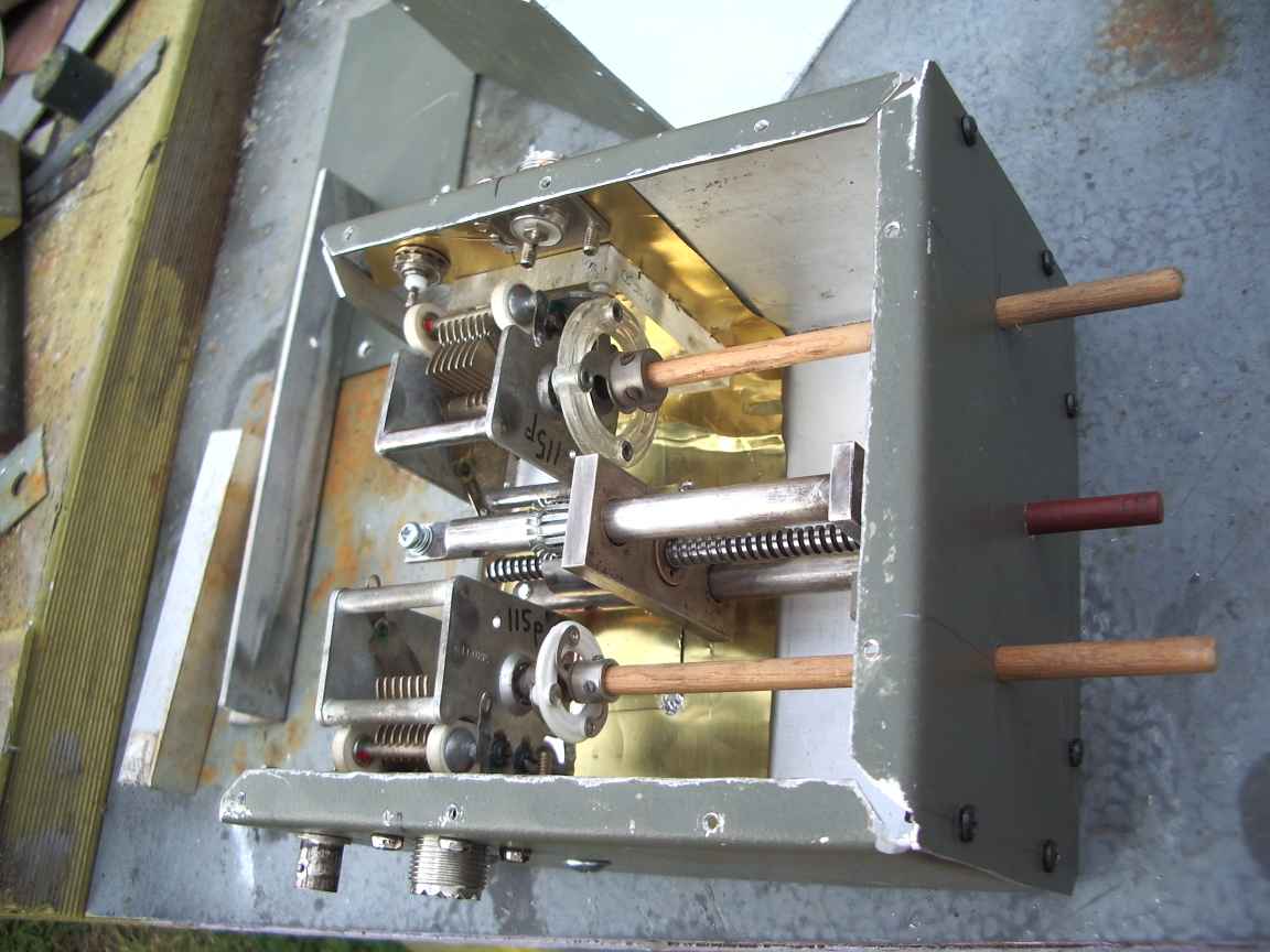
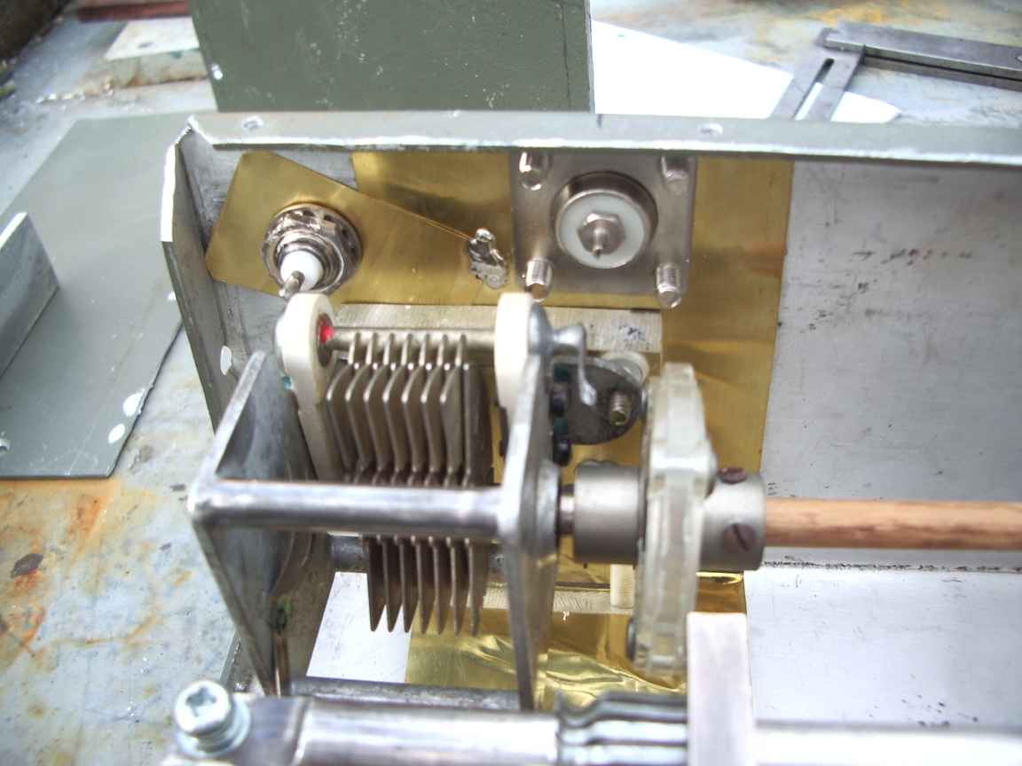
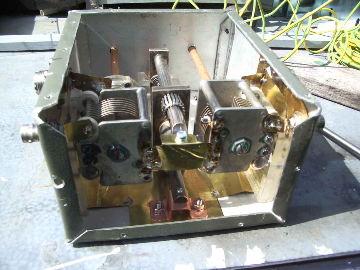
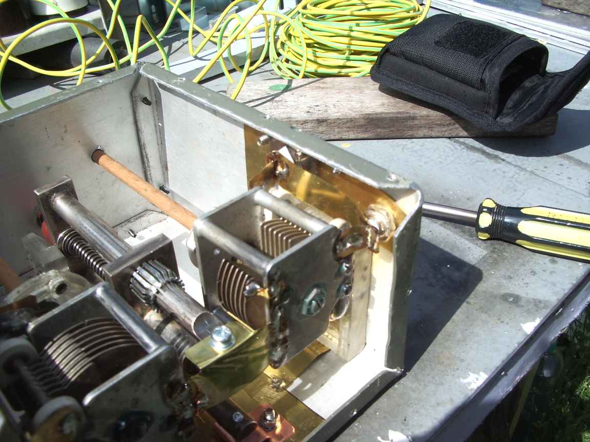
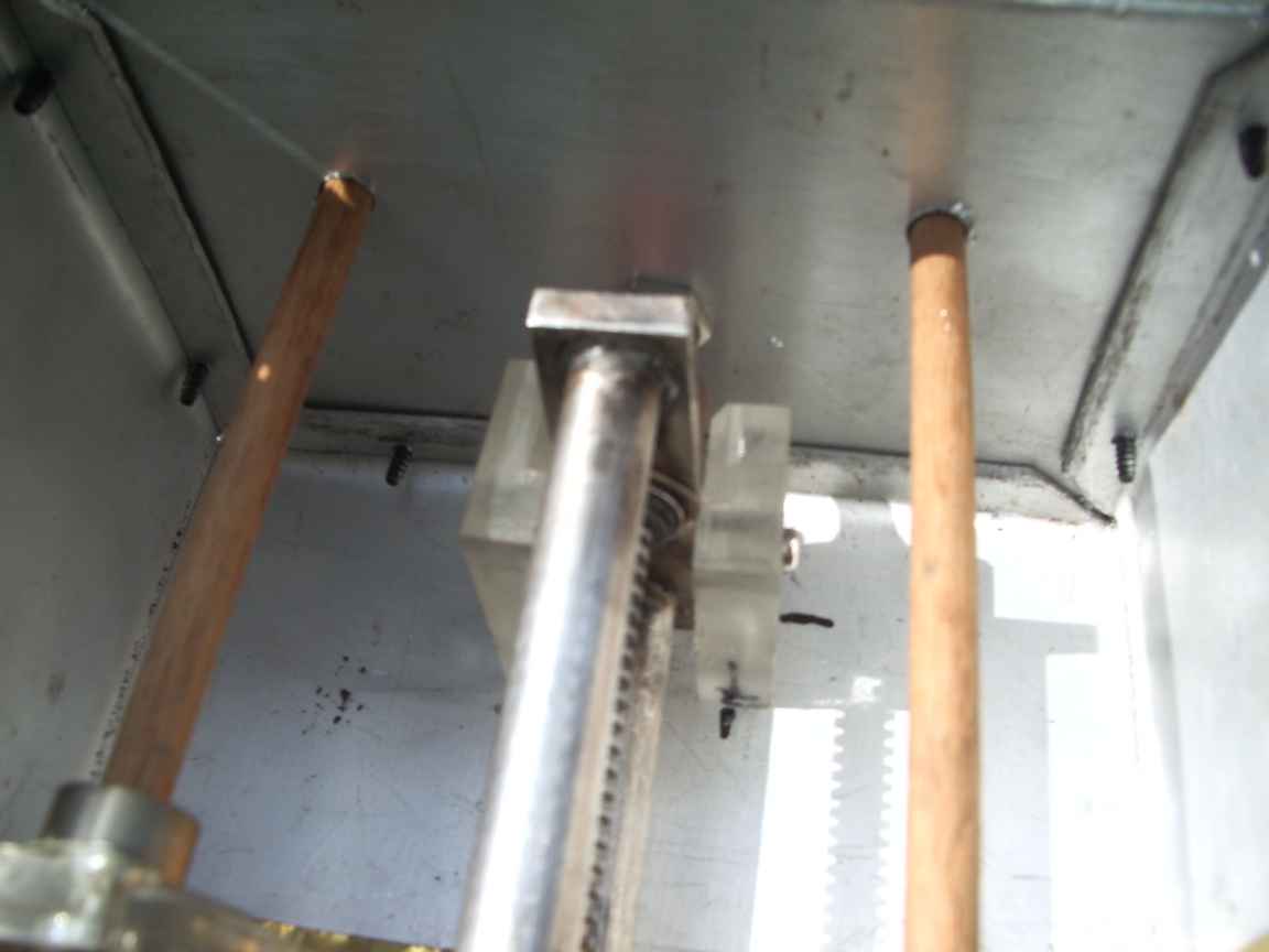
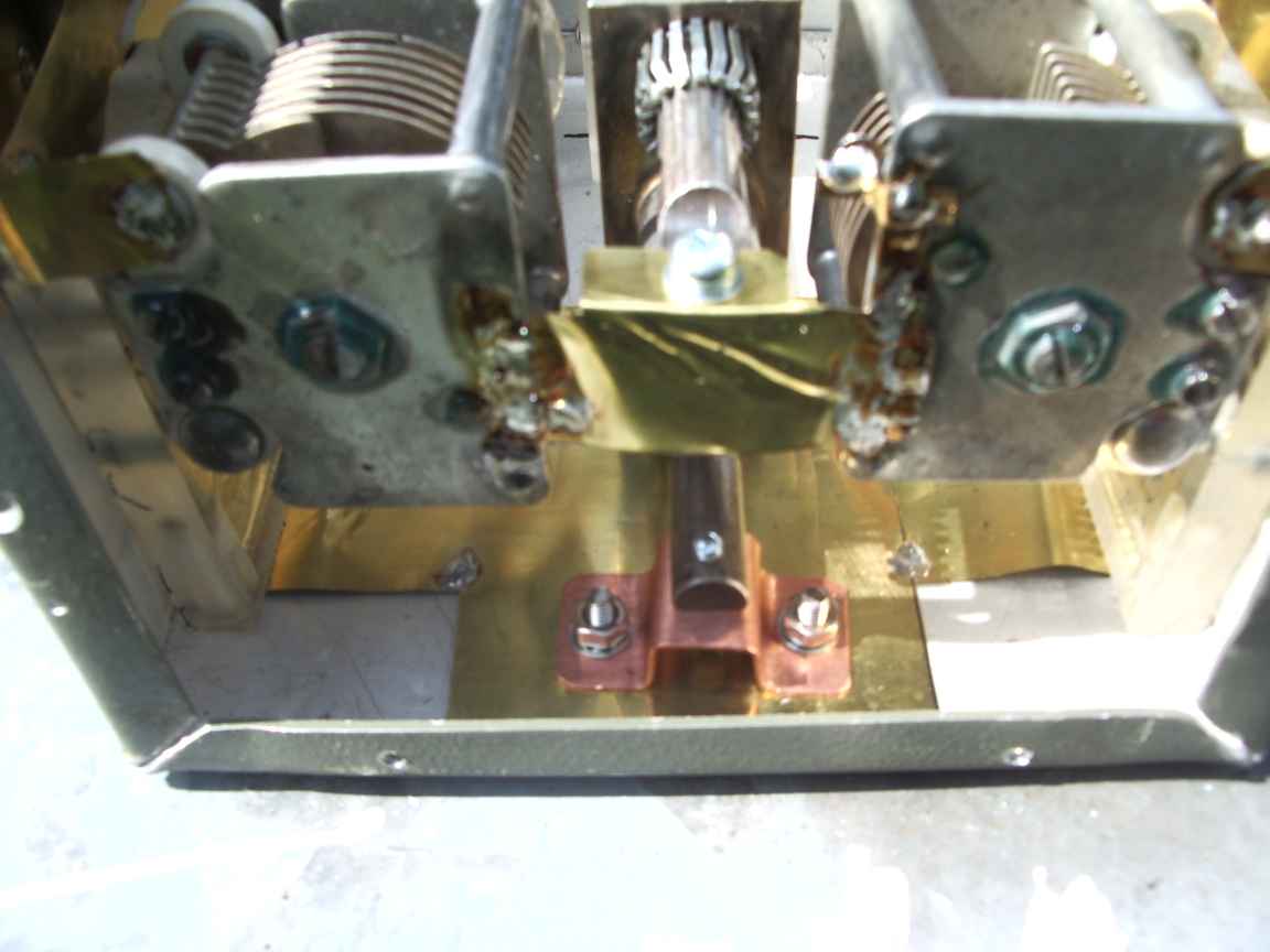
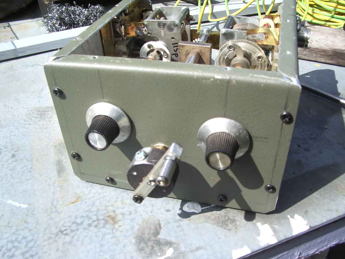
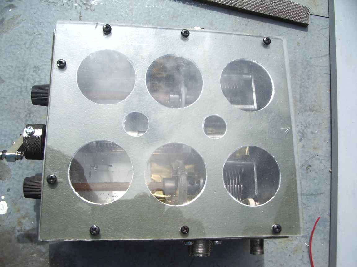
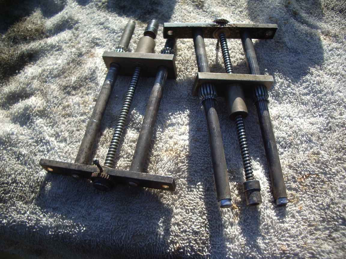
An Antenna tuner for 2 Meters An Antenna tuner for 6,4,3 Meters by VK3ZZC August 2016 There is not much point having an antenna tuner for 2M. If you have significant VSWR on your line you will have significant line loss anyway, so merely disguising this with an ATU will ,at least, make your transmitter a little happier. There are very few options for ATUs for VHF. Roller inductors have way too much inductance up here and also too many spurious parasitic resonances to be usefull. You cannot really switch a fixed tapped inductor for the same reason. A real ATU still requires some sort of variable inductance. (susceptance for all you Smith charters !) This design is a basic high pass T match tuner, nothing new to see here. However what is new is my variable inductor. It is nothing more than a variable short circuit, but at VHF has a usefully small amount of reactance to make a VHF tuner a practical reality. This "inductor" was purchased at a recent hamfest. It must have sat at the bottom of the prior SK owner's junk box since world war two. This is probably the actual truth. It originally would have been the output tank of a WW2 vintage radar oscillator or output amplifier ground station for VHF air band. Its solid construction and heavy silver plating says world war2 surplus. I dithered for a while over this relic at the hamfest, it came with a handfull of assorted junk and I really do not need more boat anchors. I felt that if I did not bite, I would regret it, as this item is made from unobtainium. The variable capacitors came from my junkbox, which I have been hoarding for over 40 years ! It was time they left home a got a job . They also came from a piece of WW2 surplus that I had found on a hard rubbish collection all those years ago. The choice of Olive Drab vinyl finish on the case material was just coincidence, I just happened to have scavenged a large sheet of this material. The case was hand made by myself so the sole reason that the total path delay through the tuner had to be minimized. The RF ports must have the minimum practical path to the capacitors so this required this custom box to be beaten into shape. There is just barely enough clearance for the short circuit slider to clear the capacitors and base. The box is lined with brass flashing so as to provide a good low resistance path for the coaxial connectors. The capacitor shafts must be insulating, I have used 6MM wooden dowel that has been shaved to 1/4inch for the legacy hardware. The shaft couplers were a necessity due to the lack of precision in my box construction. The reason for the holes in the top of the case is to permit visual inspection of where the inductor is up to. I could engineer some sort of turns counter, but visual inspection is best. I still will add some sort of ruler at the bottom to calibrate the slider. The handle on the knob of the variable inductor really is needed. Turning a knob twenty times is hard work without the handle. I have found that the most satisfactory method of tuning this device is to use a return loss bridge, a wide band noise source and the 2M transceiver as a sensitive detector for the bridge. Successfull tuning for my 2M J-pole occurs at about 1/4 minimum inductance and then to fiddle with the capacitors for maximum return loss . Perhaps in future years, to facilitate field day operation I should build in a little noise source for tuning purposes with external return loss bridge. I now have more faith in the operation of the RLB then any SWR meter I have yet encountered. The true null setting is hard because all three controls are interactive with the T Match. Start with the inductance for the first null and fiddle with the capacitors for a perfect null, seems to work for me. I believe that this could well be the first practical antenna tuner for the 2 meter band . I have seen nothing significant in numerous ARRL , RSGB, et al handbooks. The limiting factor was always the lack of a practical variable inductance at this frequency. This unit does work and I would urge its reproduction to those lucky enough to be able to source or make the sliding short circuit. It still remains to be said that at VHF your antenna should be designed and matched at the antenna end of the feedline. An ATU should not be required. Its only purpose is to make your commercial transceiver a little happier. It may have automatic high SWR power reduction protection. An ATU like this can make an appallingly bad antenna into a merely bad one ! |