2 Meter Band linear amplifier for SSB service
by ralph klimek VK3ZZC May 2016
The rationale for this project was to try something unconventional and to re-purpose some coomponents and modules that I had acquired from various dumpster dives and hamfests over the years. The main use will be for 2 Meter Band SSB on which I have limited capability thanks to an old but good TS-700 all mode radio that I got at a hamfest for only $100 that only puts out 5 watts.
Why do I like 2 meters sideband ?
Since 1976 , most of my real activity has been on 2 meters. This was largely due to having licence restrictions that limited activity to 50Mhz and above. Thankfully, that restriction is gone , however, I still like 2 meters due its unique coverage and ubiquity. You can always get a contact on FM. The perception of communication range is set by the collective ham experience on this band, and that experience of is defined by FM. How far can FM really go anyway ? The answere is not very far. This lesson came home during the last JohnMoyle field day. With my newly repaired device I was able to hear SSB stations at ranges that are science fiction on conventional FM. My lowely 5 watts was able to achieve two way communication that are impossible on FM on high link loss paths. So now I want more talk power on SSB. Linear amplifiers are still expensive, even at hamfests, so the decision was reached to do something about it and also make this a learning experience.
The options are not attractive on my budget. Thermionic or solid state ? Transistor power devices that are easy to use and high powered are still very costly and require the use of hard to get components like RF rated mica chip condensors. Then there is the design learning curve with strip line reactances. Thermionic is the next choice. I have a collection of good bottles. This needs really high voltage and much metal work and much time.
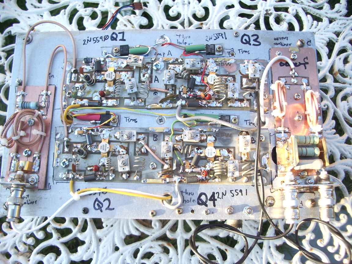
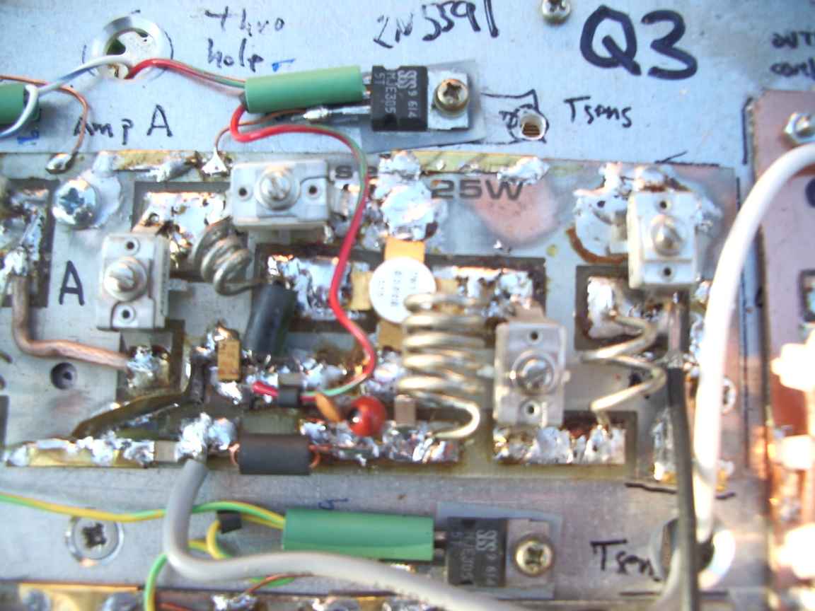
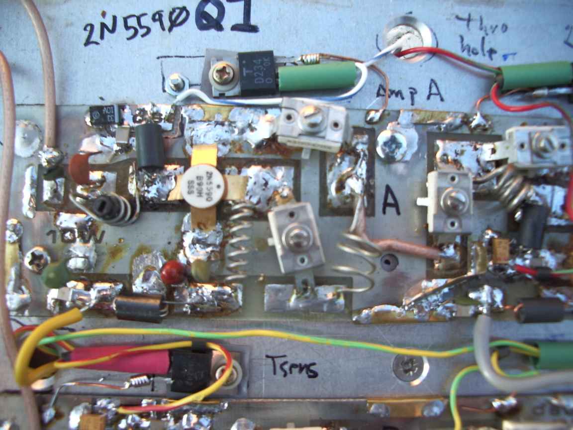
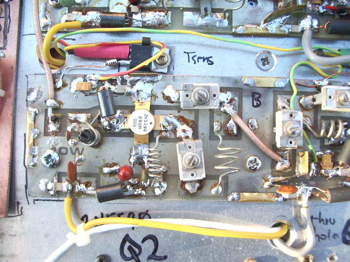
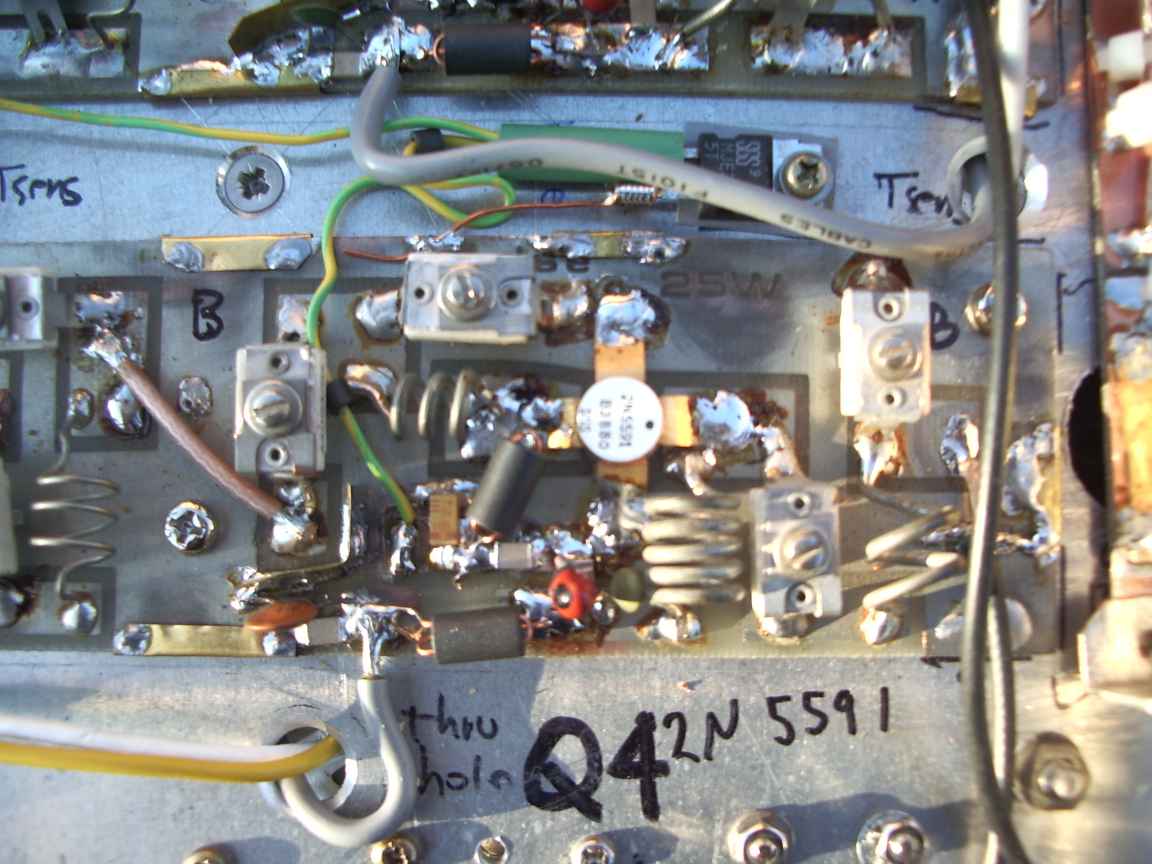
At a long forgotten hamfest I bought a handfull of these small power amplifiers for a few dollars. Most of power transistors were dead and the images shows the survivors. They are not even very good transistors, very low gain and not even designed for linear service , they were designed for VHF Hiband class C amplifiers and are about 30 years old or worse. Could I do something with them other than construct yet another FM classs C brick amplifier ? The modules actually came from a very old Dick Smith Electronics (vale) DIY kit and use a very old before stripline were invented design using discrete LC networks to perform the impedance transformations. Not being able to specify with any real precision the required reactances, ceramic mica trimmers were used. Good, this is a technology I am comfortable with, we have room for error . A stripline design is better, but, if its wrong you need a new PCB. It must be completely designed right the first time or else nothing usefull will happen.
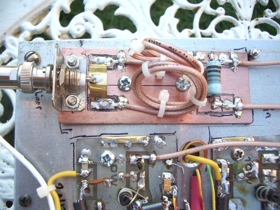
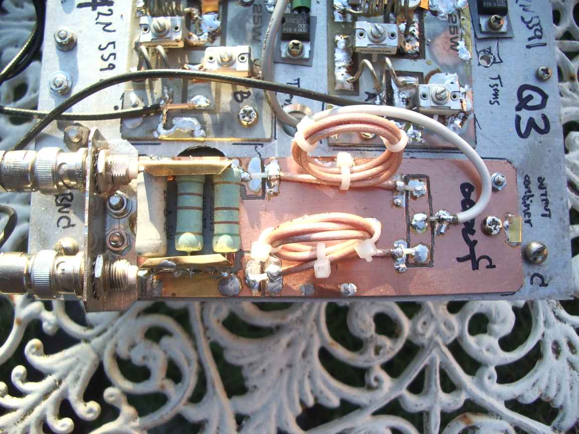
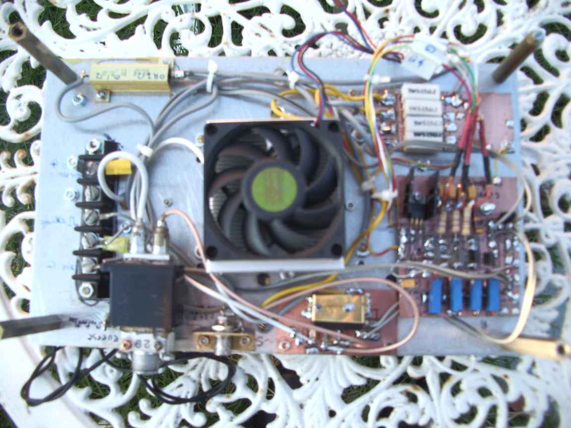
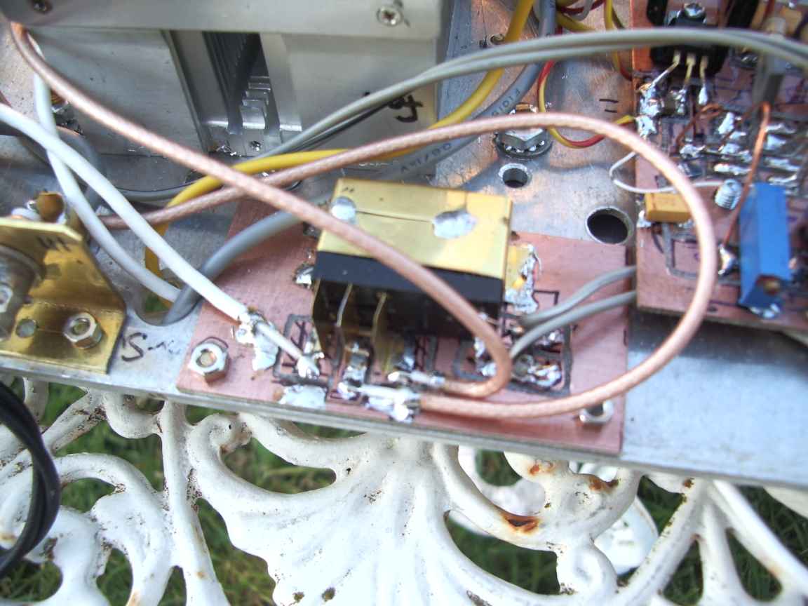
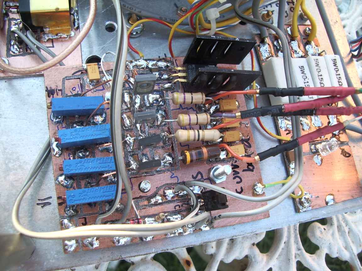
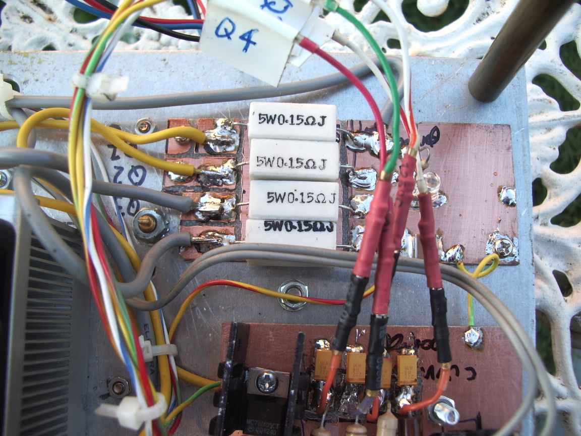
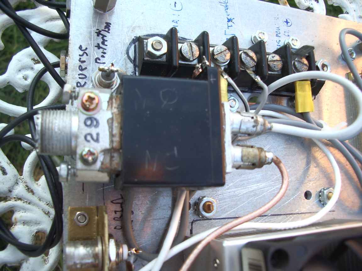
My modifications and repurposing efforts here are challenging to say the least. I am using 2N5990 2N5991 Class C transistors for linear service (bad) and I am putting two amplifiers IN PARALLEL . What could possibly go wrong ? Unlike reference designs I am not using a flat finned heatsink. The baseplate is slab of 6mm aluminium scrap. The heatsink is a repurposed computer heatsink. These little heatsinks can easily remove 100Watts worth of power and my expect maximum dissipation will not exceed 50 watts. There are base bias "diodes" in very close thermal contact , so I am not expecting bias difficulties. There are 2 willkinson power dividers on input and a combiner on the output. I hope they provide sufficient isolation to prevent one amplifier from killing its companion. The combiners are made from 75 ohm teflon coax and noninductive resistors.
All circuit boards were cut out with a TCT rotary tool on a DREMEL. its faster than etching and you can add afterthoughts as required.
My target performance is to get 40 watts PEP of SSB from this arrangement. This is a usefull amount of power on 2 meters.
Have I powered it up yet ? Nope.
