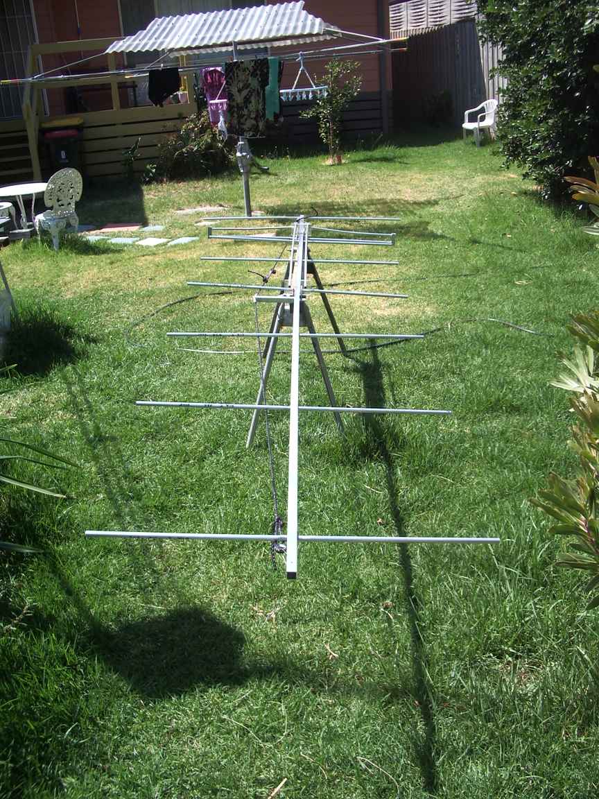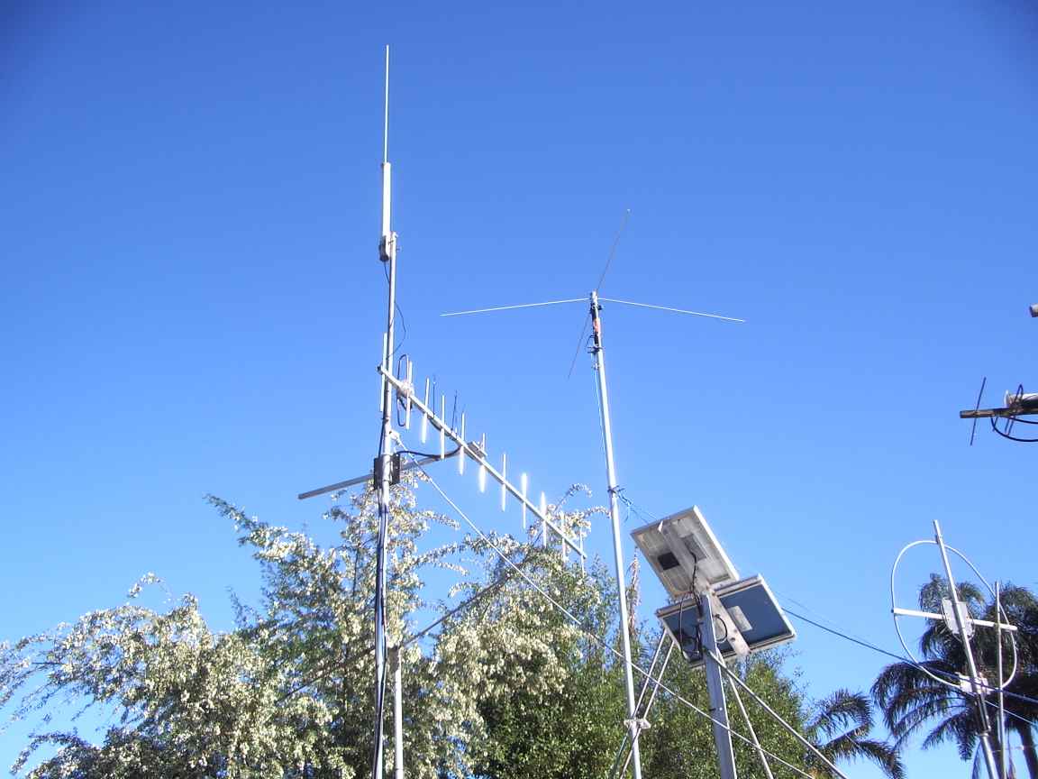
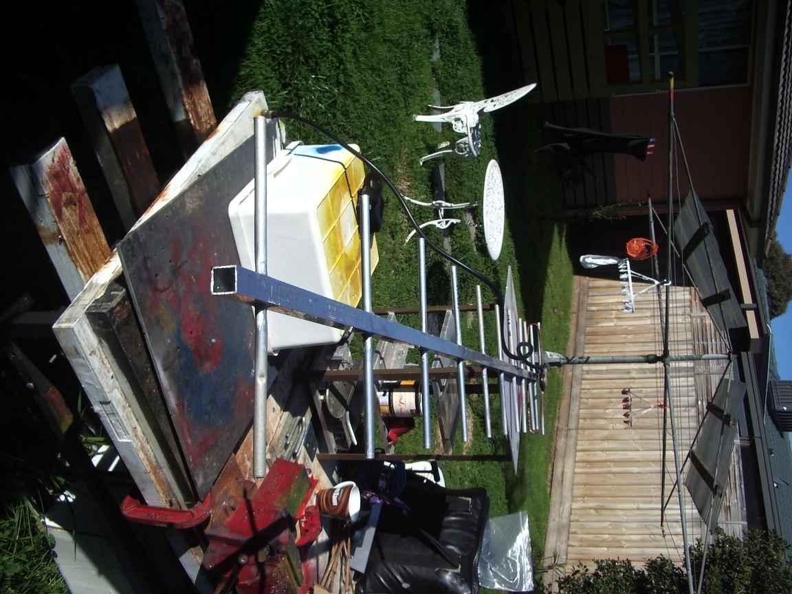
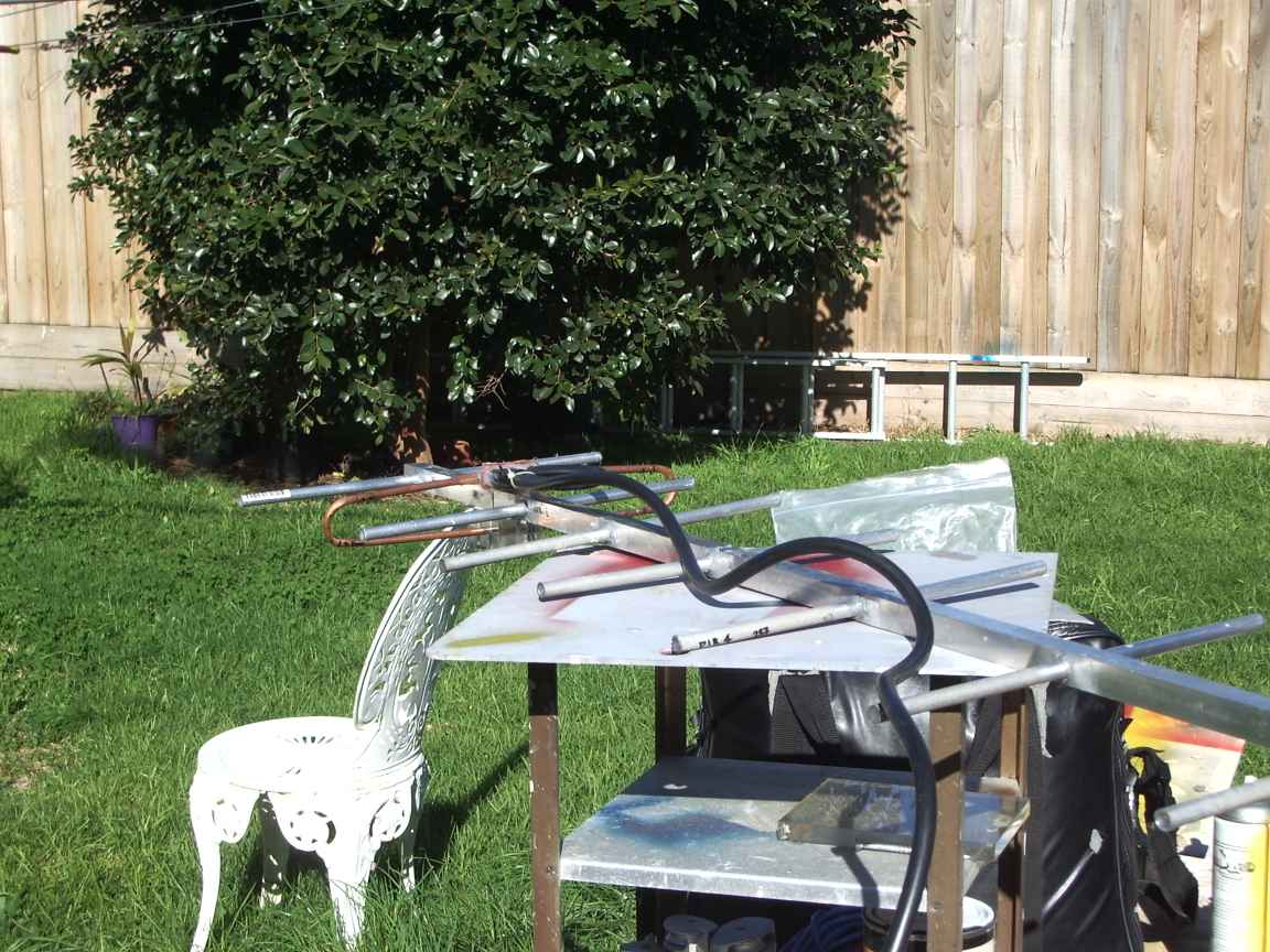
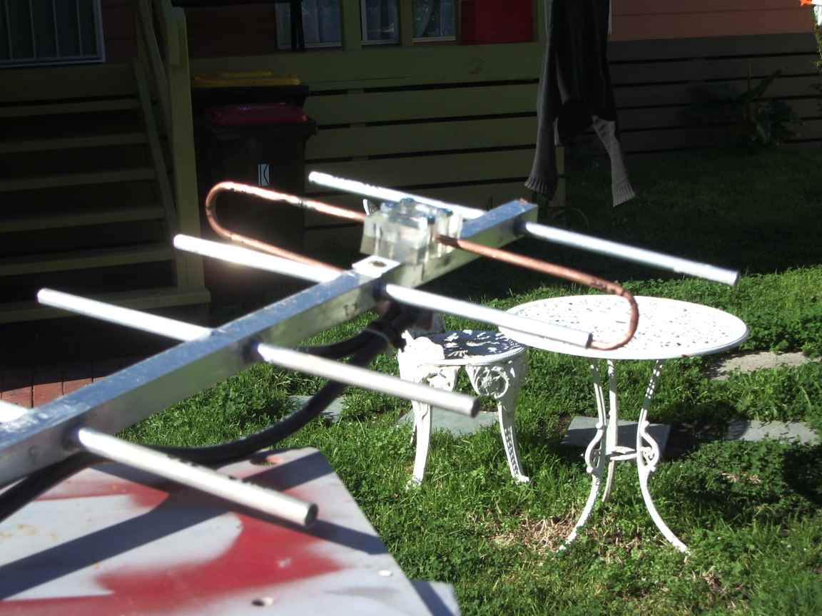
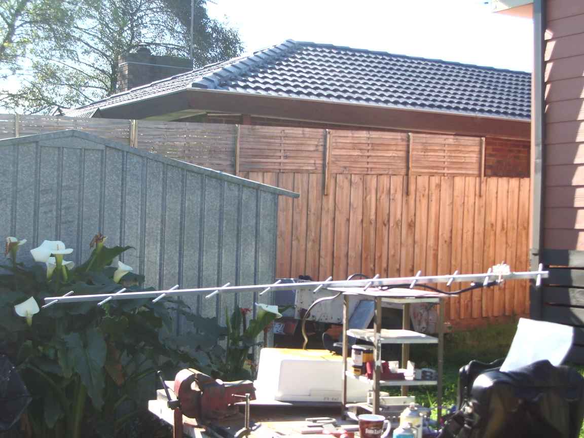
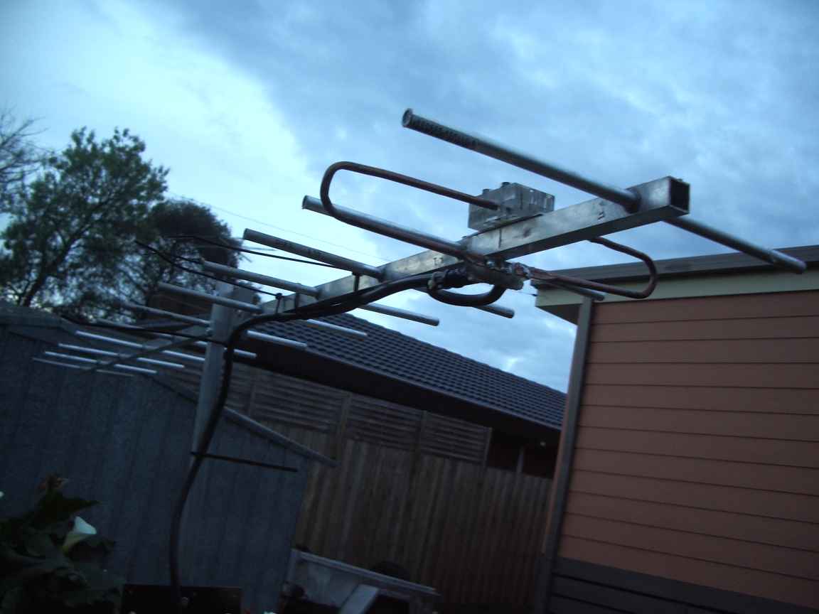
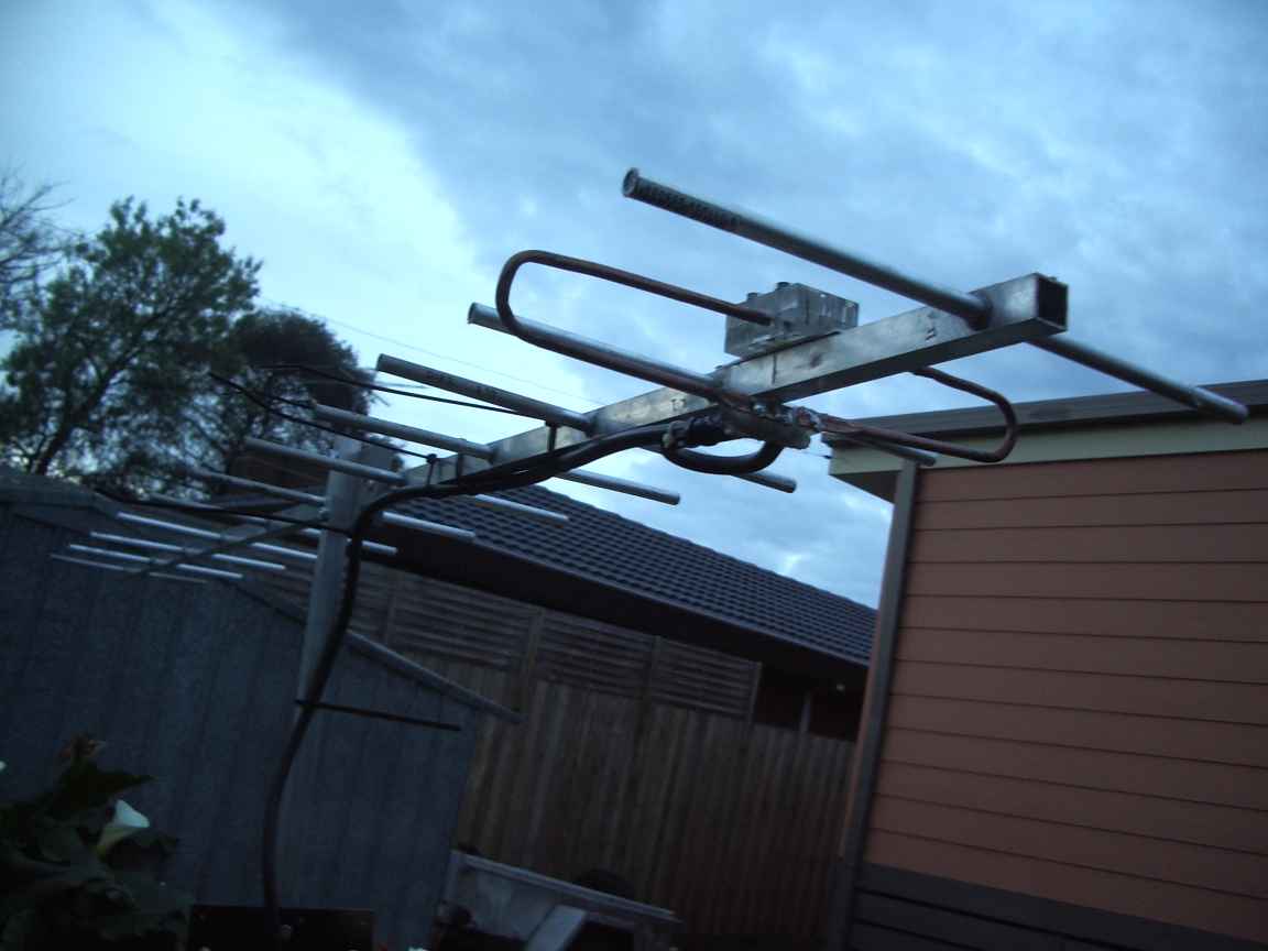
abstract. This antenna features 10 directors, all metal boom. It has a reasonably wide bandwidth as far as yagis are concerned. It is also , I would hope, readily reproducible. My experience with yagi design copied verbatim from such sources as the ARRL Handbook has been bleak and disappointing. I have discovered the hard way that high gain yagis are almost irreproducible because you must use the exact dimensions and this also means using the exact hardware the original constructor used. Optimized yagis are even worse. If it is EME or tropo-scatter that you do then very narrow bandwidth and a fully optimized design is your requirement where every little dB is precious. The average Ham (if there be such a thing) requires mainly low cost and reproducibility with readily available ,non specialist, locally sourced hardware. The average ham requires bandwidth more than the last half dB of forward gain. Bandwidth and forward gain are mutually exclusive and with this issue you must make your own deal with your devil. This yagi was designed by computer , http://www.vk5dj.com/yagi.html so I will have some faith in its prognostications given that the inputs to this program include the material and dimensions of whatever hardware I have on hand or can source from the local hardware shop ! It will automatically optimise the reflector to driven element to first director spacing to provide a 50 ohm match with a half wave coaxial balun. This program also works on the garage-penguin with linux and wine. The real point of this article is not just to encourage you to copy my antenna, but presented here are some construction techniques that you might find valuable for your own custom yagi array. |
Critical dimensions and considerations for a yagi include:
My prior successfull yagis have all been based on non-metal booms, these just seem to work. This is my first all metal yagi attempt in nearly 30 years of hamming it up. |
My summary of prior success for compromise yagis has been:
When I feed my compromise design into yagimax or a mininec clone, it shows that this design has reasonable gain and bandwidth but at the cost of large sidelobes. For typical ham use, the presence of sidelobes is not all that objectionable. It is nice to be able to hear other stuff to the side of the boresight. So then, my all metal yagi required
point 2, my recent discovery of aluminium brazing permitted my to make true metallic bonds of elements to boom. These are HIGH CURRENT connections, nothing less than welding or brazing will work here point 3 the feed point impedance of a simple dipole element in a yagi may be as low as ONE OHM ! and a folded element inherently multiplies this upwards by four into something more manageable. point 4 a square section extrusion is easy to drill ! You allready know how hard it is to drill a good truly centred hole in round tube ! point 5 the computer design adjusted the spacing to permit a coaxial balun feed bonded directly to the driven element. What if I wanted to now use a differant frequency ?, or the modeling program was just wrong ! point 6 nothing kills the desire to make or copy something when unobtainable hardware is specified. |
So then, my all metal yagi required
|
point 1, it was about time I tried an all metal boom. Real advantages, if you can get it to work, simple hardware required, like NO special element mounting hardware at all. Lifetime construction. point 2, my recent discovery of aluminium brazing permitted my to make true metallic bonds of elements to boom. These are HIGH CURRENT connections, nothing less than welding or brazing will work here point 3 the feed point impedance of a simple dipole element in a yagi may be as low as ONE OHM ! and a folded element inherently multiplies this upwards by four into something more manageable. point 4 a square section extrusion is easy to drill ! You allready know how hard it is to drill a good hole in round tube ! point 5 the computer design adjusted the spacing to permit a coaxial balun feed directly to the driven element. What if I wanted to now use a differant frequency or the modeling program was just wrong ! |
My
past experience with yagis, ( and you can proove this yourself with the
many mininec derived modellers) is that the radiation pattern ( gain )
is only mildly affected by element spacing and dimensions but feed point
impedance is critically affected, that is why I like universal stubs
as any implementation will have accidental and incidental
tolerances that are beyond the constructors control. If you need to
minimise sidelobes for professional beam shaping reasons then you have
no choice but to use a heavily optimized design. |
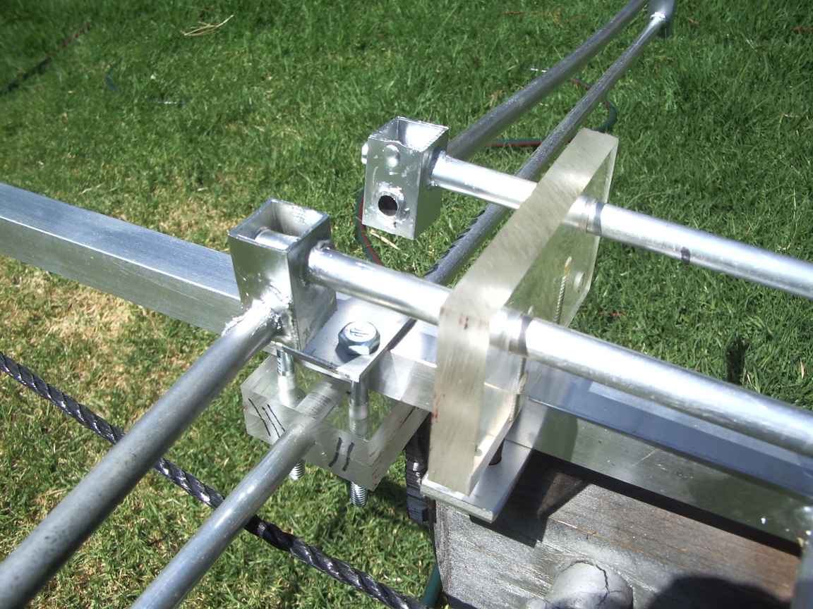
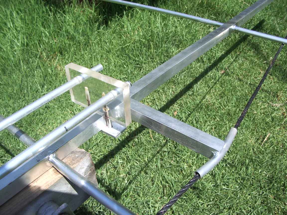
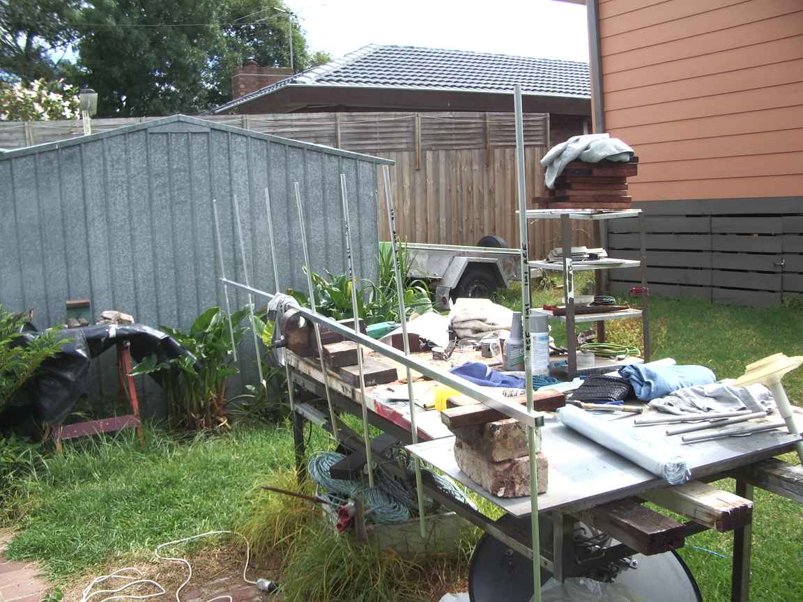
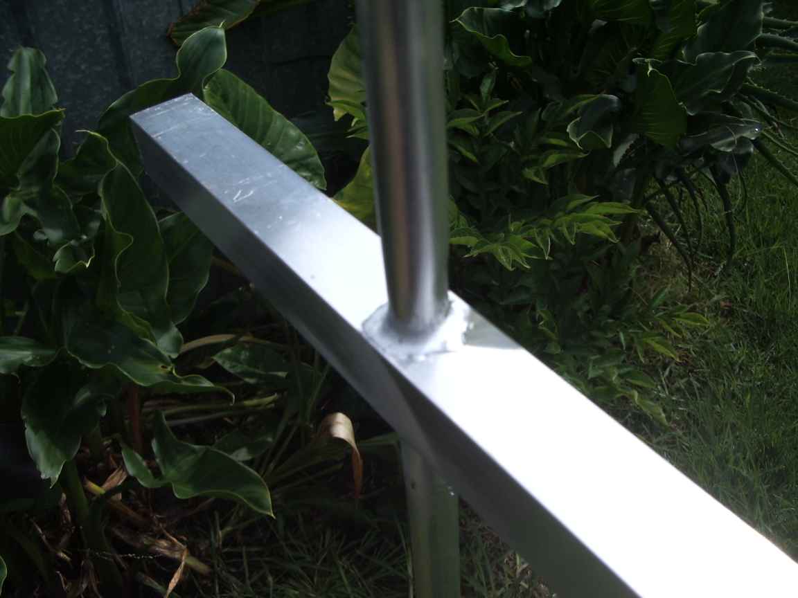
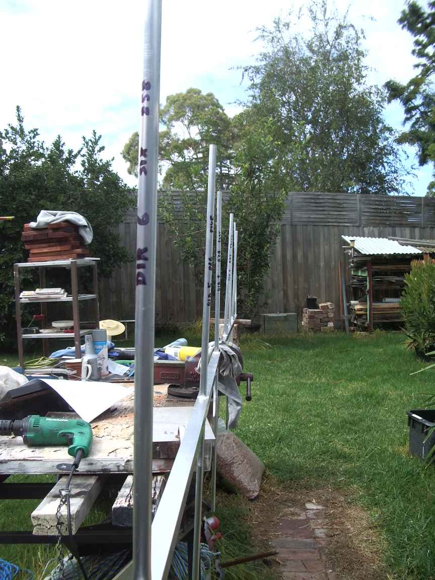
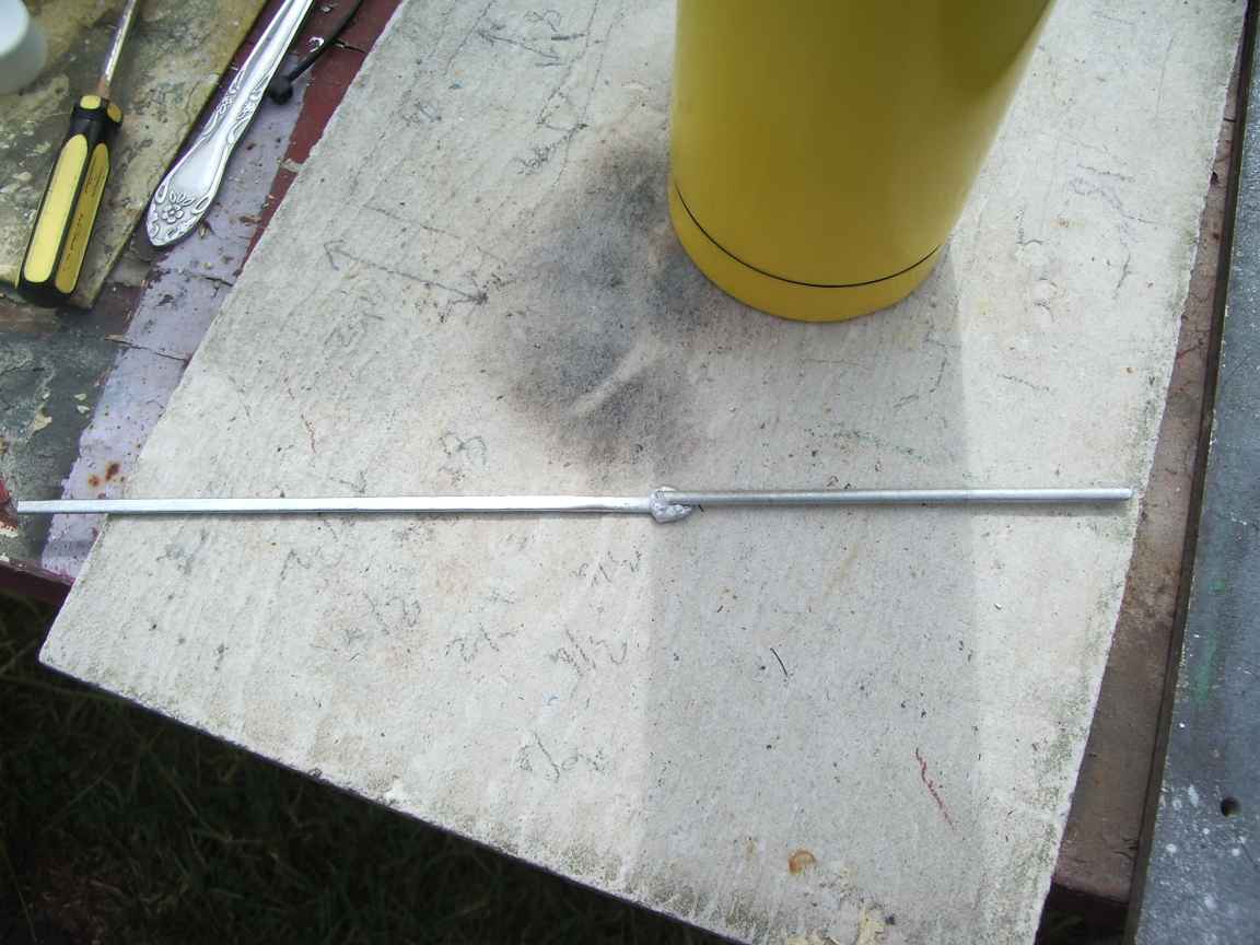
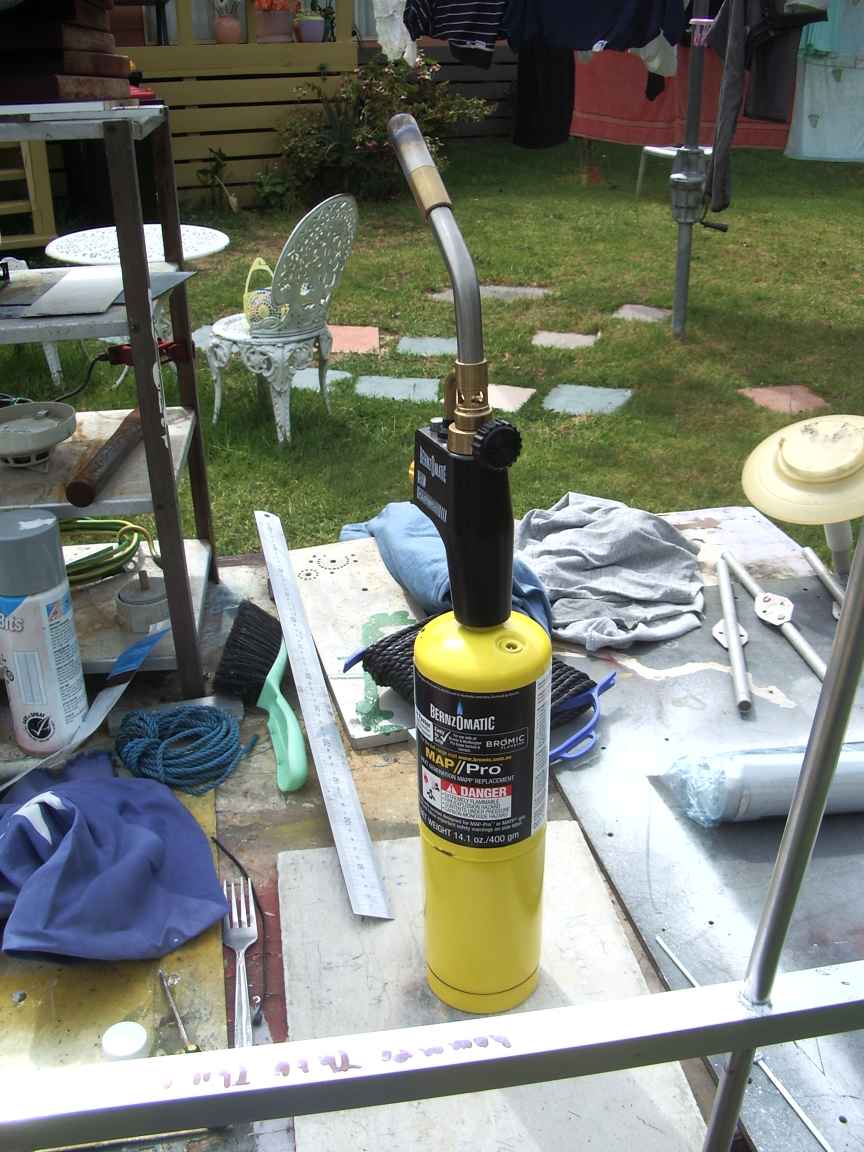
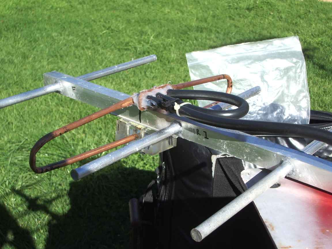
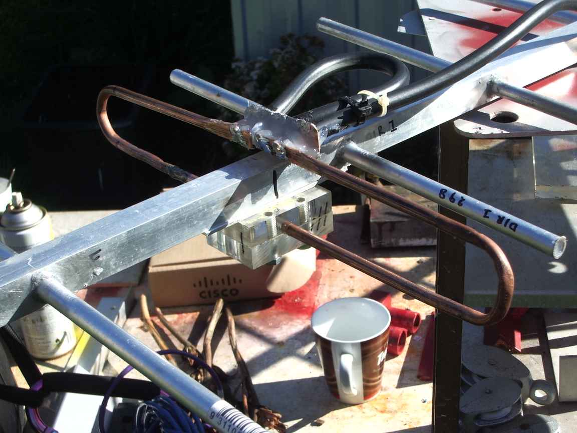
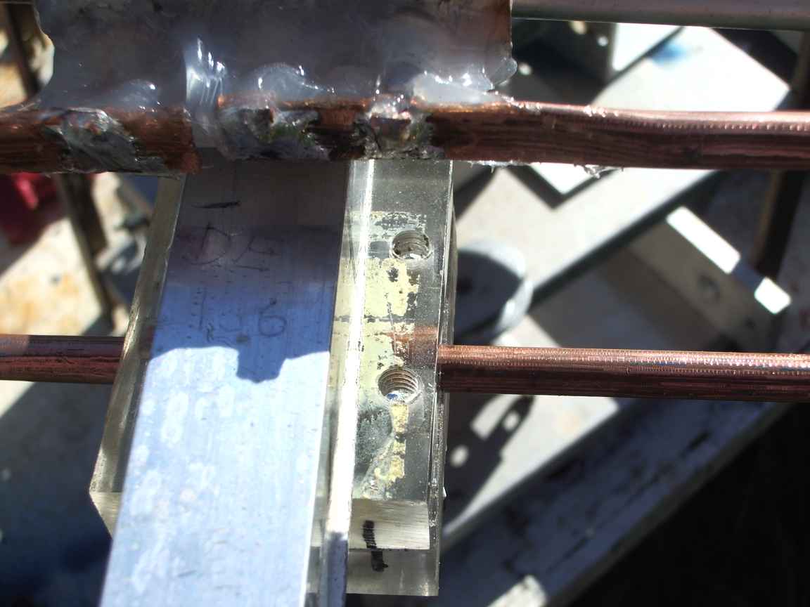
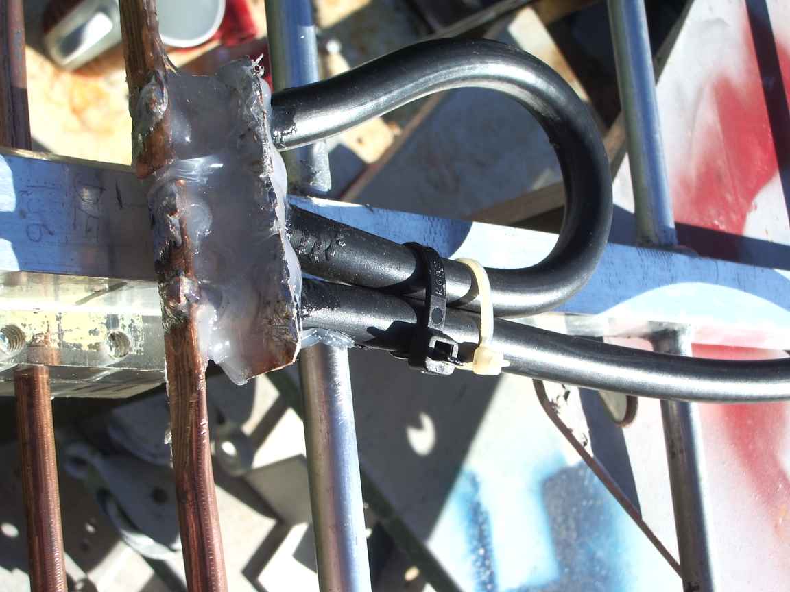
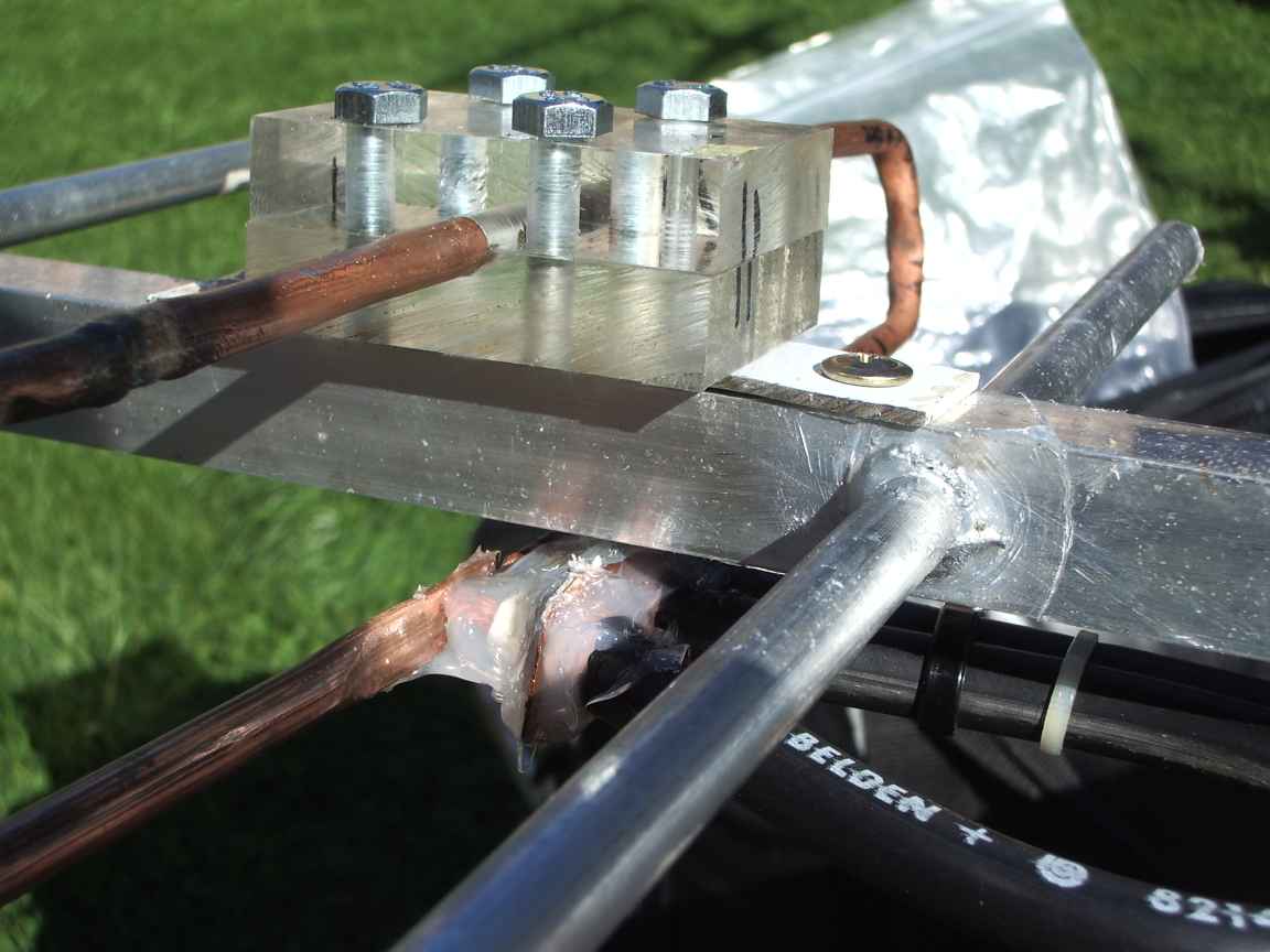
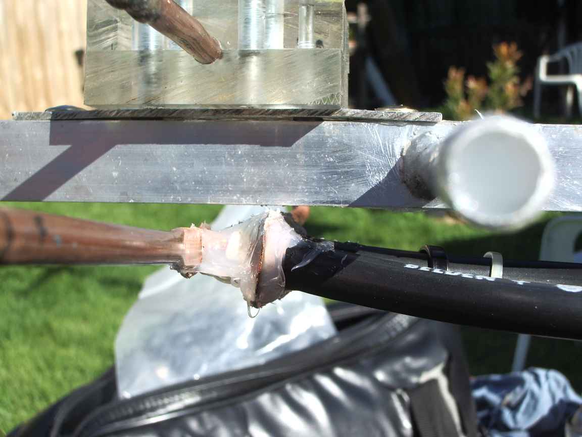
Construction notes It is alleged that the dimensions are critical. This is probably true ! It is only true if the designed feed point impedance is to be achieved ! I have not added a universal stub. This may change if I wish to move away from my design frequency of 440 Mhz. Use 20mm square extrusion for the boom. With Square section it is easy to drill a perfect perpendicular hole . Drill a 10mm hole for 10mm tube stock. This will make a sturdy interference fit . Gently tap the element into the boom. This force fit is ideal because when we braze the joint it will not move. Use a drill press to make the hole, a hand held drill makes a hole too big for an interference fit. Chamfer the end of the element before inserting it. Measure twice, cut once ! Symmetry is important with a conducting element to boom joint. Measure, measure and just to be sure measure it again ! The element ends are sealed with silicone to prevent water and vermin ingress. I used up all my ten year collection of 10mm tube offcuts I had been saving for a project just like this. The offcuts were quite corroded , so clean them with steel wool or one of those new fangled stainless steel coarse scouring pads because we will be brazing this metal. It also helps along with the force fit. The driven element is made from copper 1/4 inch hydraulic pipe. Do not ground it, it is not possible to find the true electrical center point of the driven element, so, let it find itself by mounting it in an insulator. It does not need to be grounded to the boom. The coaxial balun is soldered directly to the driven element. Thats why I choose a copper element ! It is vital that you prevent water ingress into the coaxial cable, so be very generous with the silicone rubber. I recommend foam insulated cable for the balun. This will make the balun section slightly longer then solid di-electric coax which makes fabrication easier at 70cms. Take care soldering foam coax, it is easily destroyed by excessive heat. The outer conductors of the coaxial balun and feed line was soldered directly to a piece of heavy copper flashing. This flashing does not have to be grounded to the boom. At low VHF we would do this, but at UHF it is too hard to find that true zero voltage ground point. Through holes were drilled through the flashing , using this tool, the braid splayed out and directly soldered to the flashing. blank PCB would also be suitable for this task. The feed line is made from a section of heavy 50ohm foam dilectric coax and fitted with a silver type N plug to permit a directional coupler to be placed there for the testing and commissioning phase. Do not scrimp on this or think you can get away with it. Test the finished antenna while it is still on the ground on your bench. It is too late to do this when it is out of reach high up on your mightily impressive tower. The force fit is quite reliable for mechanical purposes but is useless for RF currents. This joint is a high current point and every dB is precious ! The joint must be brazed to create a true metallic bond. See also howto solder to aluminum. Here I have used just a propane torch and Benzomatic Aluminum Brazing rod. ( Durafix and Alumalloy are the same product ) I had to wrap the nearby boom section with rag to give it a bit of thermal insulation because the propane torch puts outs only just barely the required heat. This rag may catch fire, so do this procedure out of doors. Do not do this with any ambient wind or it will too readily conduct the heat away before we get to brazing temperature. Indelibly Mark your measurements on the boom with a scriber so they do not rub off whilst under construction. Indelibly Mark your precut elements with length and element number. It is amazingly easy to confuse yourself as they all look the same ! The braze metal being a ternary alloy will quickly corrode under atmospheric conditions, so protect it with a smear of silicone rubber. The best silicone rubber to use for full sun and atmospheric exposure is the heavy glazing/guttering grade with the acid cure. Yes, that is ACID cure. The acid is only acetic acid which is not actually that corrosive to metal. However the rubber will give you at least 25 years service in the full Australian sun...that IS impressive. (Been there, done that !) The driven element insulator was made by securely clamping two pieces of perspex and drilling the hole straight down through the join. Have you got a cheap drill press ? No ? Get one! This wont work with just a hand drill. You cannot drill an interference fit in the boom with a handheld drill. | |
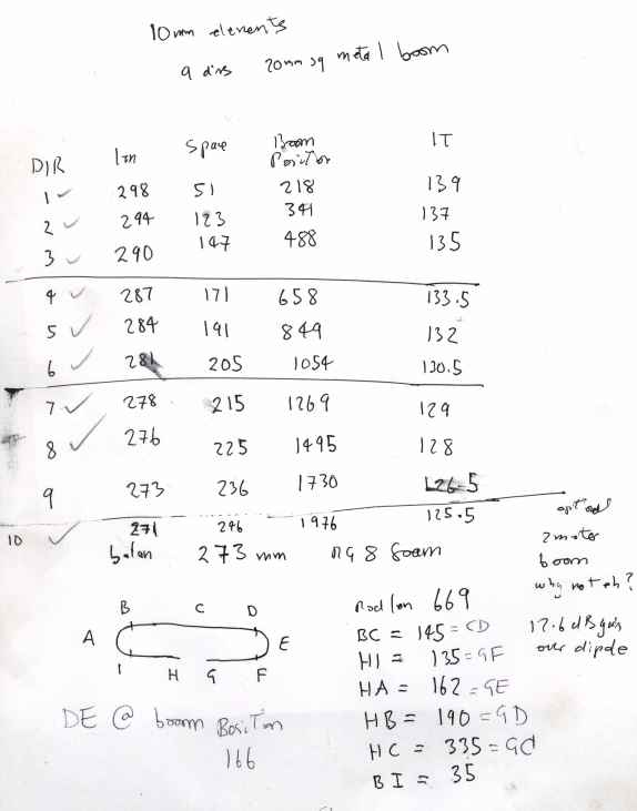
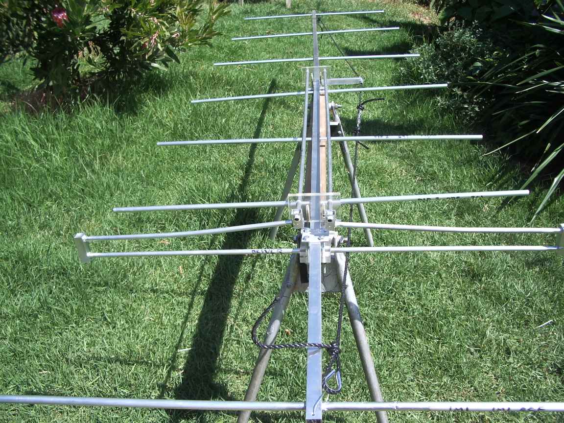
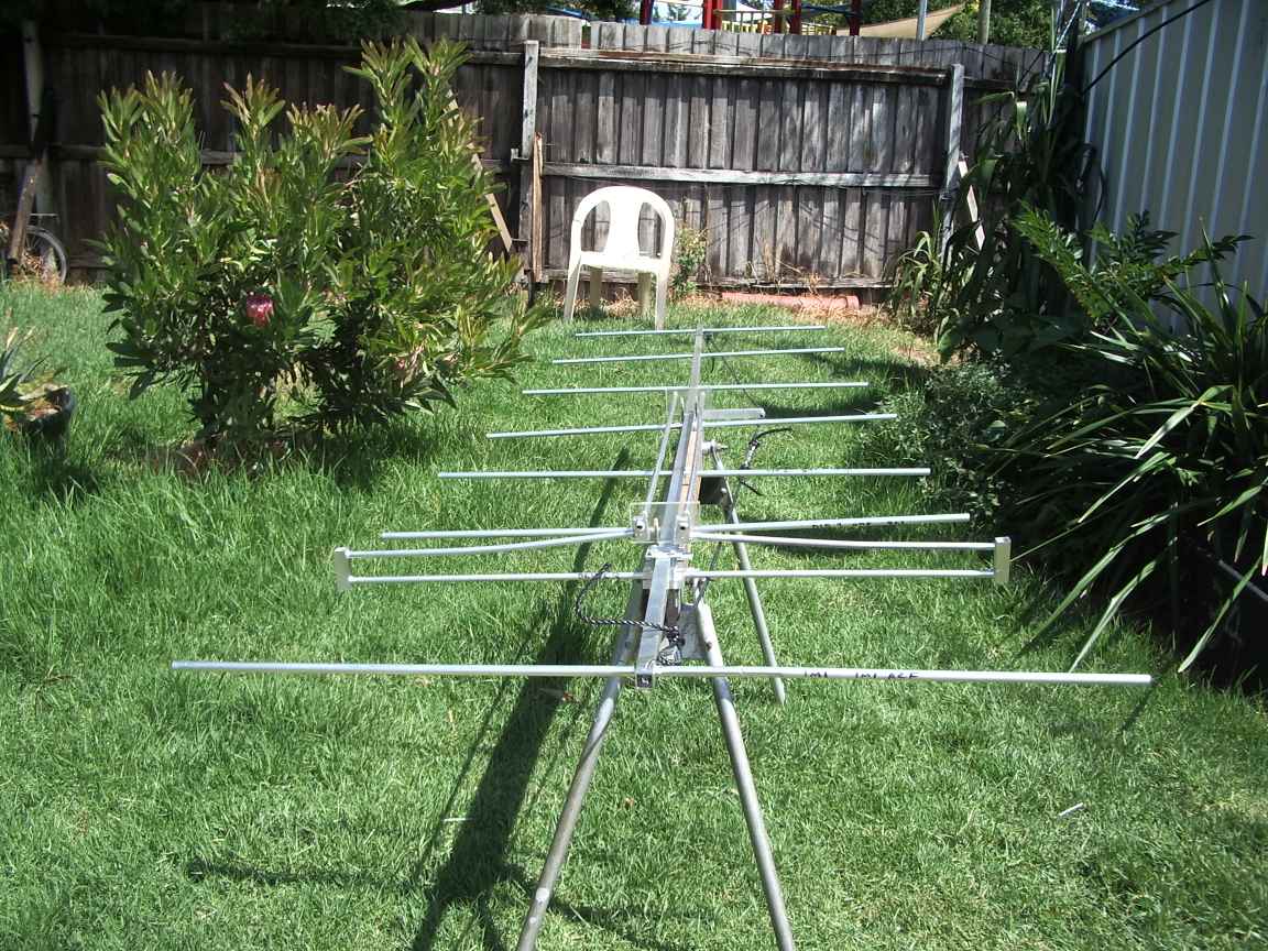
design for 440 Mhz , reflector at 30mm from end of boom. Boom position means mm from physical end of boom. The modeling program predicted 12.6dB gain over dipole. Nice. WE SHALL SEE ! |
Will I make a 2 meter version of this ? Well I did. I wish to take part in the crossband sessions with VK3ASE (1863khz ,top of your dial !) who accepts programme input on 145.3 Mhz and relays it on 147.475 Mhz. This is a difficult thing to do as no matter how hard you try to meddle with resonators etc, reciever desensitization is nearly impossible to overcome. This antenna is an attempt to open the squelch at VK3ASE. (no line of site but about 20kms suburban downrange ) This all metal 2M yagi will supplement the 70cm aerial and also serves as a test project for all metal yagi design. It is not hoisted yet, still to do, design and complete the universal stub matching element..sliding contacts and shorting bar....and test. One of my design goals was not to make any penetration into the boom other than elements. The reason is that mounting holes and and screw holes seriously weaken the boom and permit water ingress. The element to boom joints are brazed all round and done properly will not contribute to boom weakness or permit water ingress. The driven element and stub mountings are designed to permit the driven element to director spacing to be varied so as to give additional choice of feed point impedance. I used , http://www.vk5dj.com/yagi.html to design the this beam. Mine, off course is a variation on the design to permit usage at differant frequencies. I designed it for a target 145.3Hhz, but one day will also repurpose it for 144.1Mhz so additional flexibility was required, notably the universal stub. I have deliberately increase the reflector length to accommodate future 144.1Mhz activity, I expect this will result in extra sidelobes, but the change in design means the computer model's feed impedance is no longer valid.....hence the additional of the stub. My experience over the years will yagi antennas shows that the radiation pattern is sensibly insentive to frequency , but feed impedance is extremely dependant on frequency, so some practical means of local, at the antenna , adjustment is required. The braze and aluminium form an electrolytic couple, so some kind of passivation is required, I use aluminium paint which appears to be weather resistant. | ||
low impedance point, feed into driven element. contacts all positively brazed metalurgical bonds. Driven element is isolated from the boom with homemade perspex insulator. | rear end of universal matching stub. designed for vertical polarization, this guy provides mitigation for boom sagging. Perspex found by dumpster diving at industrial sites | boom is 3.3 meters, expected gain circa 10dbI, probably get at least 8 dBI. The turn-buckle provides just enough tension to stop the boom wobbling. |
I will be writing this up in greater detail in the fullness of time, however hospital duty, 3 ways as visitor,client and service provider have curtailed my activities this year. | ||
under construction in the sky shed | true metalurgical element to boom bond | under construction in the sky shed |
Above, all metal element to boom direct brazed joint. With the slightly thicker 3mm square boom material, it conducted heat away from the joint too quickly , a propane torch could not supply enough power. I use and highly recommend the Bernzomatic Propylene burner which does have the required power. This is "poor man's acetylene", not as good as the real thing but extremely effective for me. They are ,however, quite expensive to buy . The gas refills are moderately priced, the brazing alloy rods are very expensive. That is five dollars worth, on the left. braze your stubby leftover bits together so none is wasted. |