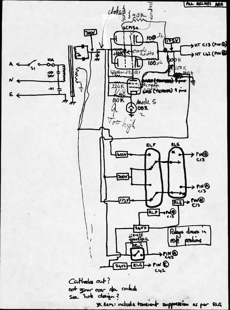
I was sufficiently disenchanted with
the power unit, and not having a schematic was not in a position to
improve it. Due it is high component density reverse engineering was
out of the question. Instead I measured the power harness under various
operating conditions and built a mains powered PSU from old television
components to emulate its behaviour. I had purchased the 12E1
bottle a year before for all of thirty cents. I thought the large
surface area of the bottle and the large anode had to be usefull for
something. Its still a favoured bottle for audio amp enthusiasts due to
the very cathode current possible for this super cathode emission
bottle. At this stage in my life, my only test instrument was a multi-meter.

The TV transformer DC raw supply had
an open circuit voltage of about 700V DC peak so a series pass regulator
was required to drop it down to 150V as required by the main circuit.
The regulation was good and the resultant improvement in
frequency stability caused me to use my C13 as a primary source of
carrier, variable IF and frequency calibration for the rest of my ham
radio activities.
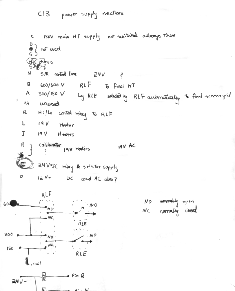


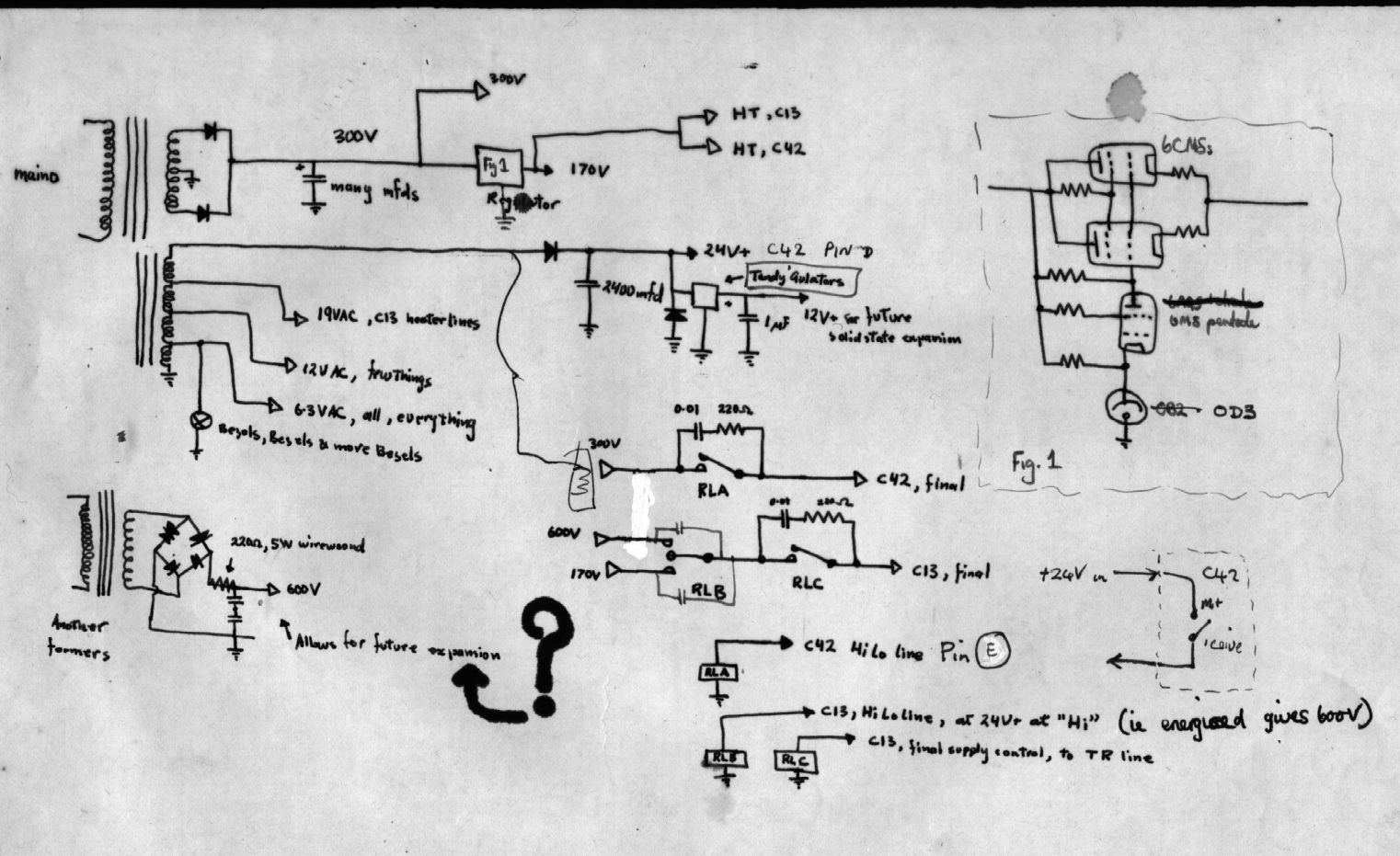
This psu design can run the C13 and the C42 set simultaneously
Dont try to copy these design, they are more my notes than a cookbook
design. these notes date from 1980 and beyond. If you must use solid
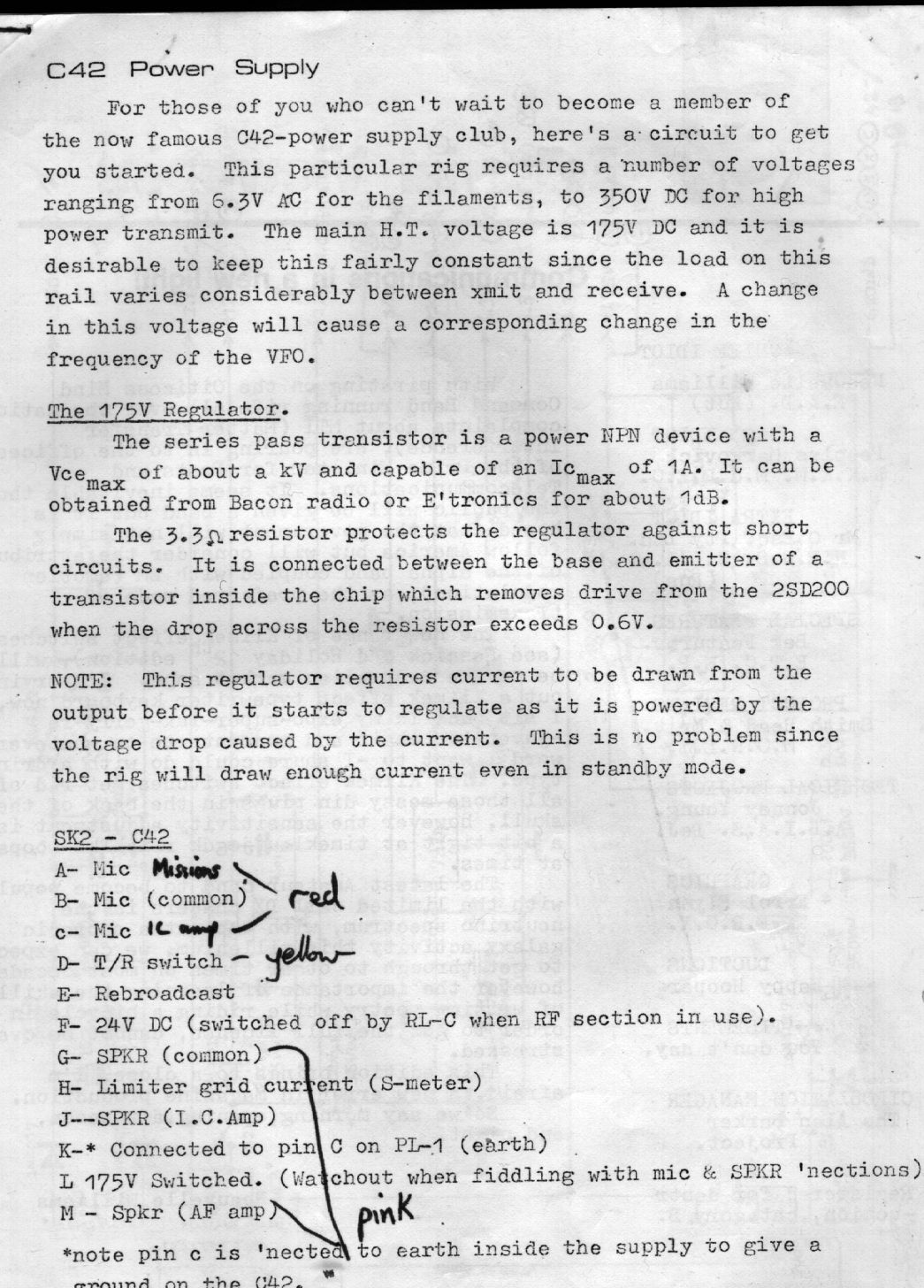
state seris pass regulators look at the solid state drawing below, but
use something more forgiving than a 2SD200, try a BUX80.
The power transformers were all sourced from discarded all valve televisions. This sort of transformer is unobtainable today, but if you come across a discarded old valve TV set do rescue the power transformer and deflection valve. Other sources of HT could be found by biulding up multiple series connected transformers of the 50 volt class. There are some of the 72-0-72 secondary catagory that are meant for the high power audio amplifier market that would be satisfactory. If you have a vibratory supply a good source of high amperage 24volts can sometimes be found in discarded data centre networking equipment. Most of these had 48volt dc supplies, but some older chassis had 24Vdc supplies. The total power requirements are about 100VA in recieve mode rising to 150VA in transmit.
The power transformers were all sourced from discarded all valve televisions. This sort of transformer is unobtainable today, but if you come across a discarded old valve TV set do rescue the power transformer and deflection valve. Other sources of HT could be found by biulding up multiple series connected transformers of the 50 volt class. There are some of the 72-0-72 secondary catagory that are meant for the high power audio amplifier market that would be satisfactory. If you have a vibratory supply a good source of high amperage 24volts can sometimes be found in discarded data centre networking equipment. Most of these had 48volt dc supplies, but some older chassis had 24Vdc supplies. The total power requirements are about 100VA in recieve mode rising to 150VA in transmit.

my triple parallel series pass 150 volt regulator made from old
horizontal deflection bottles. The 47 ohm resistor in the anode
circuits are required to prevent vhf parasitic oscillation. In fact the
first pass of this regulator effectively prevented television reception
in our neighborhood. Any old horizontal deflection valves an be used
like this. If was doing this again I would generously apply
ferrite supression beads...everywhere. These things were not
obtainable by me back in 1976.
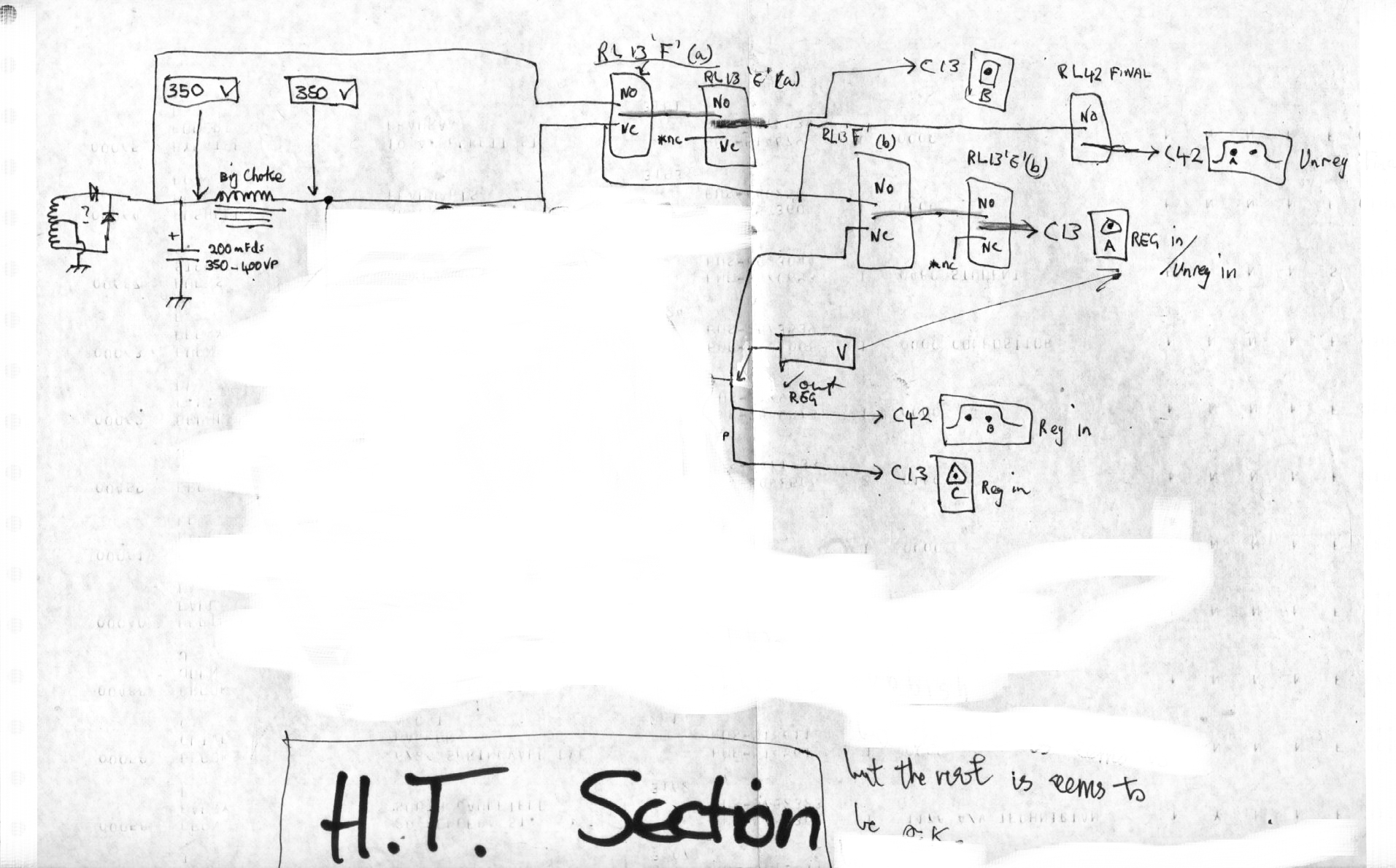
This unique solid state C42 PSU design by the Distinguished Mr Ian Holland VK3YQN
long time no see

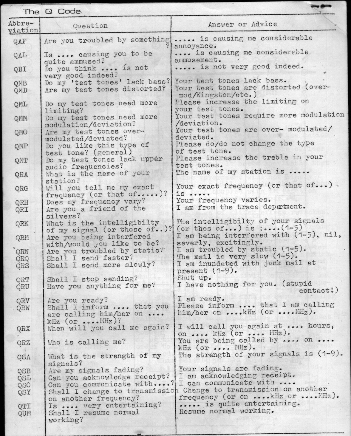
The "Q" code by an early version of Mr Irving Gribbish, 1979
from Contronics Australia
homepage

added remarks and email sig Thu Jan 7 18:07:52 EST 2010
