Reverse engineering of the
The VR299 Decstation monitor
The VR299 RGB monitor
was manufactured by the Digital Corporation. It was a very large
nineteen inch monitor for "professional use" (whatever that means)
meant to be used with Digitals' range of unix workstations like the
Decstation 3100. I had acquired on of these monitors in
1996 when 19 inch monitors were still "very cool" and only heads-of-dept were important enough to have one. I was given mine
because it was faulty and out of warranty and the repair quote
was just short of $1000.
The monitor was beautifully made,
solid ,fully EMC screened, pressed steel chassis, a magnificent Mitshubishi CRT. It has a
high bandwidth RBG video chain and a ruggedised power supply. As
they came they were not suitable for personal computer displays. The
RGB video signal came on 3 seperate 75ohm coaxial cable with a
composite XORed sync mixed on the Green signal. This was a fixed
scan rate monitor and contained circuits to detect if the the
horizontal pulse rate was outside spec and if so, to protectively shut
down the monitor. It was also insanely heavy and bulky!
The acquisition of this monitor
launched a successfull project to
convert the video and the deflection on the monitor so it would be
suitable for PC use. IT was not possible to get service
manuals or schematics from DEC at the time (now or ever!) so
I began the heavy
task of reverse engineering it so I could discover the horizontal and
verticle timing components and substitute suitable values that would permit operation on PC SVGA signal timings.
The process of deriving the circuit
consumed about two weeks. It required
totally methodical persistence and a large supply of pencils
and erasers! I have not redrawn the circuit as "enginnering
grade" schematics because it wasnt necessary for me and I had run out
of time! Even though it was a long time ago I still remember the
thrill of running it in scattered pieces on the floor connected up with
jumper wires and paperclips and getting the first sync locked
stable display of 1024 x 768 16bit colour. This was big cheese back
then. With this I could impress my friends and awe my enemies!
My reverse engineering drawings are presented here, as well as a short
paper I wrote in 1996 that documented the use of this monitor for PCs and the required modifications.
I really have no idea why these
drawing might be usefull, but I guess I am sort of attached to them as
they took me about two months of my scarce time to create. Maybe
you are repairing large CRT monitors and cannot get any schematics ?
This design appears to use the chip manufacturers application
note reference designs. This design would be representative of fixed
scan professional monitors from this era, more recent monitors make
heavier uses of VLSI for dynamic scan correction and variable scan
rates.
Sadly, the display tube in my monitor became gassy with the symptom
being that the bottom third of the display became darker and darker,
with the zone of darkness increasing in size when finally in 2001 I
bade a sad farewell to it and it continued the journey to landfill that
I had interupted. For the few years that I had it running it played
games, ran windoze, impressed my friends and awed my enemies. I
have no pictures from this era, it was before cheap digital cameras.
These reverse engineering notes were used successfully by other
radio amatuers; we finally discarded the last lab of these some time around year 2000.
or "my monitor is bigger than your monitor"
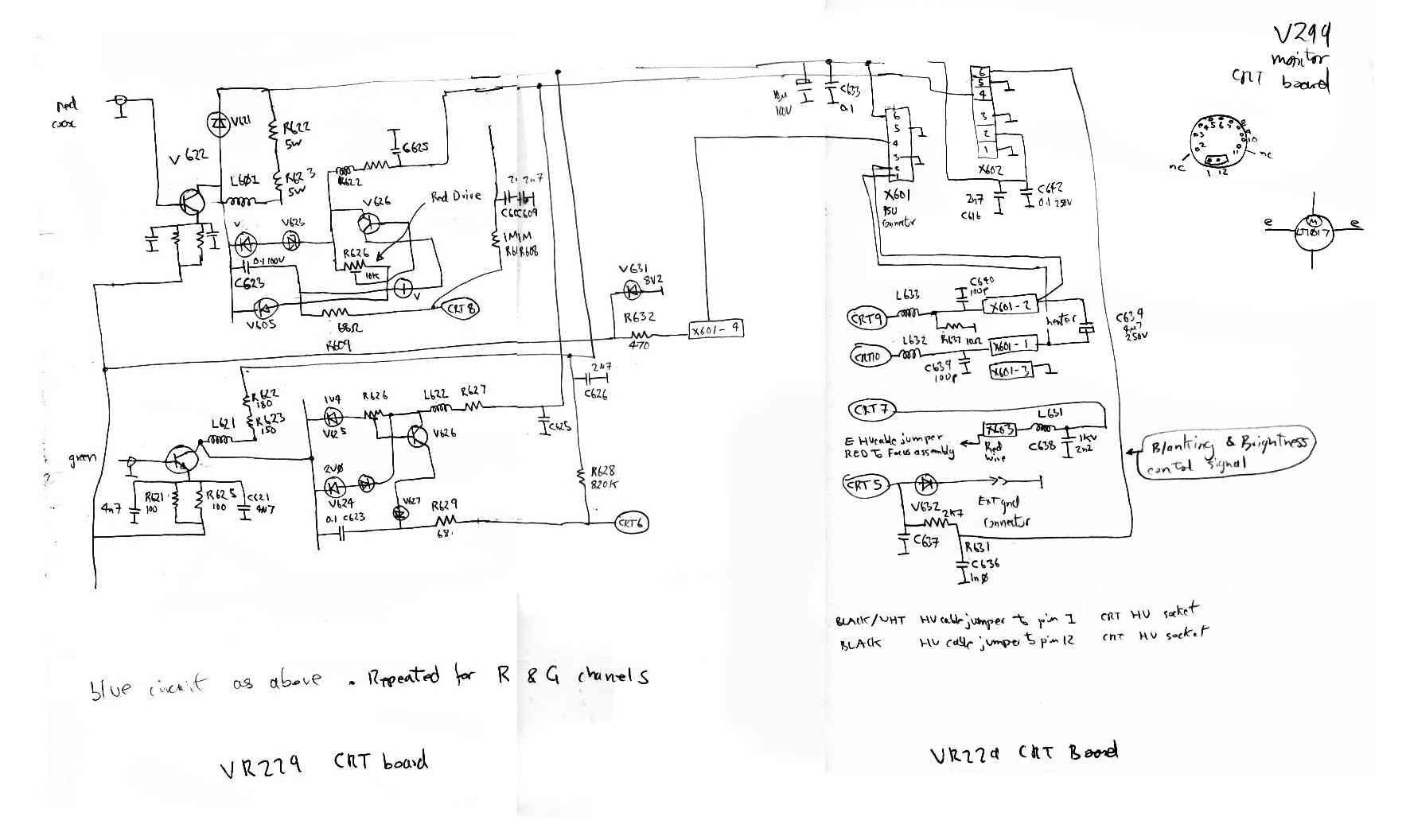
The CRT cathode drivers used MRF548 microwave power transistors and
probably the complete video chain had a video bandwidth of over 400Mhz.
Video amp also used BRF95 BRF96 microwave transistors.
This diagram shows how the differant PCB modules were linked together with their cable harnesses.
The vertical deflection system was on
the same pcb as was most of the deflection system. It was easier at the
time to derive to seperate circuits. As with the horizontal
deflection system there are elaborate function generators to correct
the scan for linearity, dynamic brightness control and dynamic focus.
The deflection system used a generic consumer TDA2653A chip but
with significant elaboration.

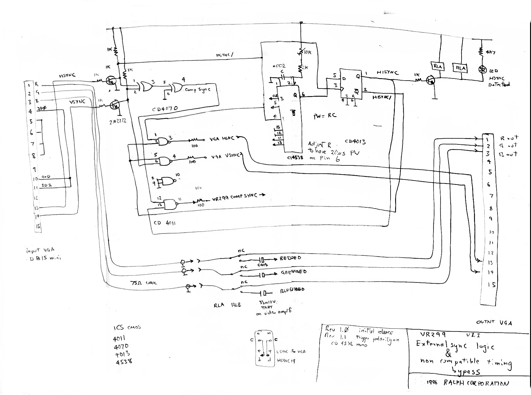
The above circuit is my sync
generator and automatic monitor switcher. The VR299 was a fixed
scan rate monitor and for pc use, with its varying scan rate changes as
it first booted DOS and then fired up Windoze made it hard to use
without a standard scan vga monitor around. The standard vga monitor
would be activated when the pc was in dos, or windoze had crashed out
to a DOS screen. In 32bit mode, the SVGA drivers and scan rates would
become active, this change being detected and latched with the
monostable and D flip flop. I reused the VR299 composite sync
seperator as this was easier. I derived a composite sync from the PCs
seperate H and V sync with the XOR gates. I used CMOS logic here
because there was a conveinient spot in the monitor that had 12 volts
availalbe. The annoying propensity of the pc to switch scan rates
was the motivation for the incredible added complexity of the multiscan
monitor.

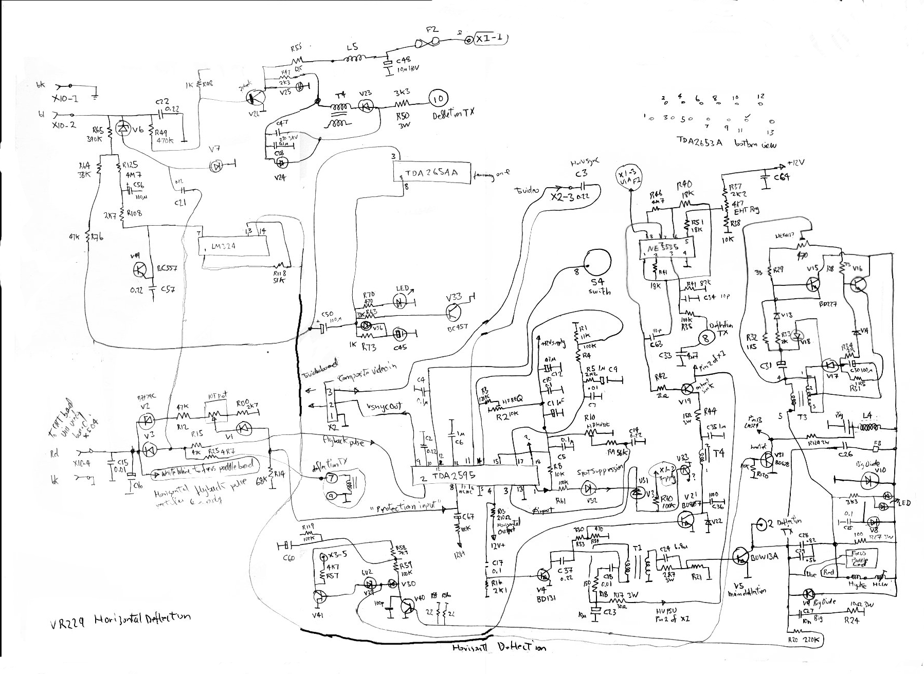
This is the horizontal deflection system. It includes dynamic coarse
and fine focus and scan intensity correction,pin cushion
correction and elaborate linearity controls. An auxilliary
winding on the scan/EHT transformer is monitored for a sustained
collapse of flux which could indicate the H sync frequency being too
low/high or a failure, this would initiate an automatic shutdown
of the horizontal deflection system.

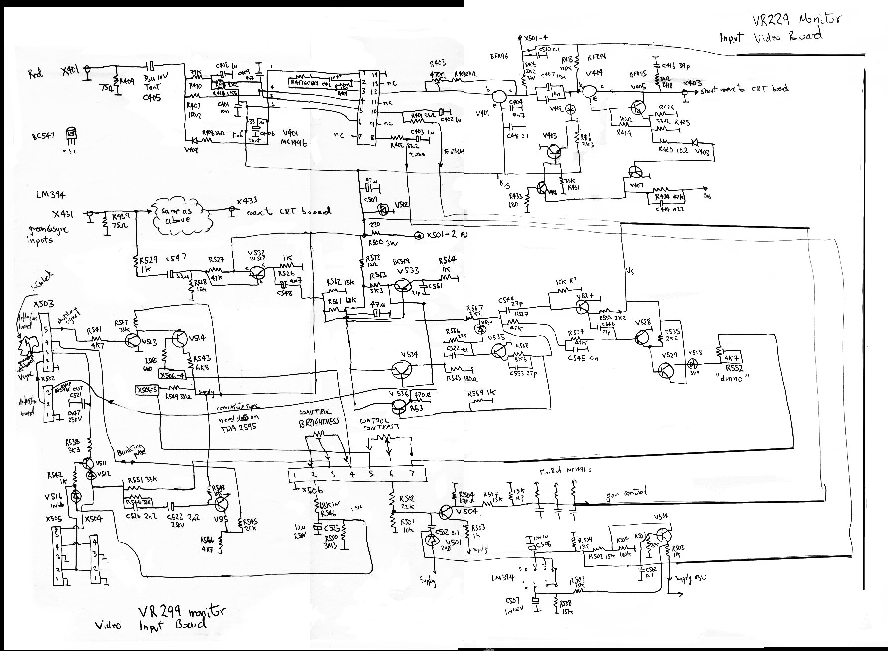
This is the video processing card.
This card was mounted on the back of the monitor and had 75ohm BNC
connectors right on the card. The video gain/offset is managed with
MC1496 multipliers and then amplified up to CRT drive level through
microwave transistors. There were three video boards, this board which
had low level video signals, a smaller board with heatsink directly
mounted on the CRT which held the CRT cathode drivers and yet another
board mounted directly on the CRT terminal pins.
But
time has moved on. In the ten years since I went to this trouble, my
converted monitor continued its interupted journey to landfill.
Nineteen inch monitors became the standard, and now corporate dumpsters
and council hard rubbish collections consist of functional nineteen
inch monitors. They have all been replaced by various LCD
flatscreen devices that are mostly horrible to look at. A real CRT
trully has an "inifinite" colorspace, whereas the LCD monitor at best
has a 16bit colorspace. At least they dont flicker, eat deskspace and
cost the earth to run. There are many dead nineteen inch LCD
monitors now appearing in hard rubbish. They are there because the
cheesy power supplies all suffer from bulging electrolytic
capacitors. This is a very easily repairable condition.
Thats a pity because there is allmost never anything wrong with
the display. Really old ones may have dim illuminators
home

