Siemens R218
Impedance and Admittance Bridge
type
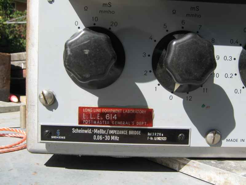
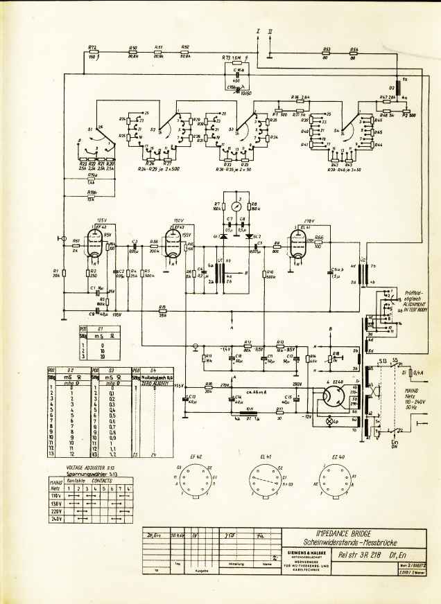
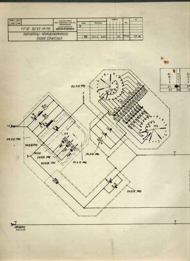
Scheinwid.-Messbr./IMPEDANCE BRIDGE
Rel 3 R 218 a
F-Nr.6/802923
Introduction
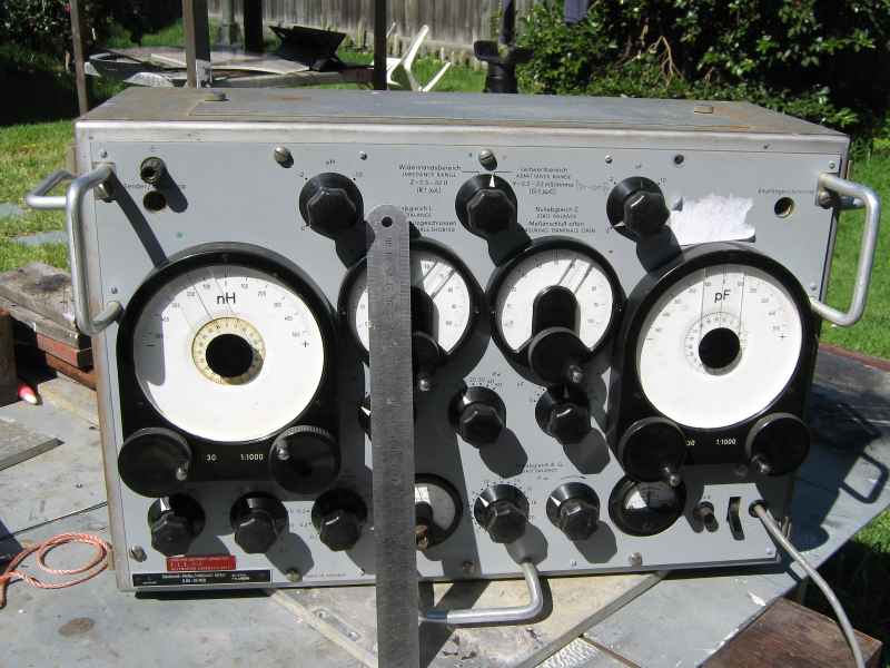
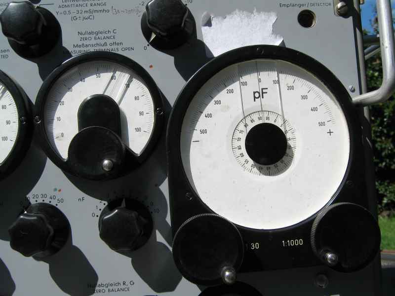
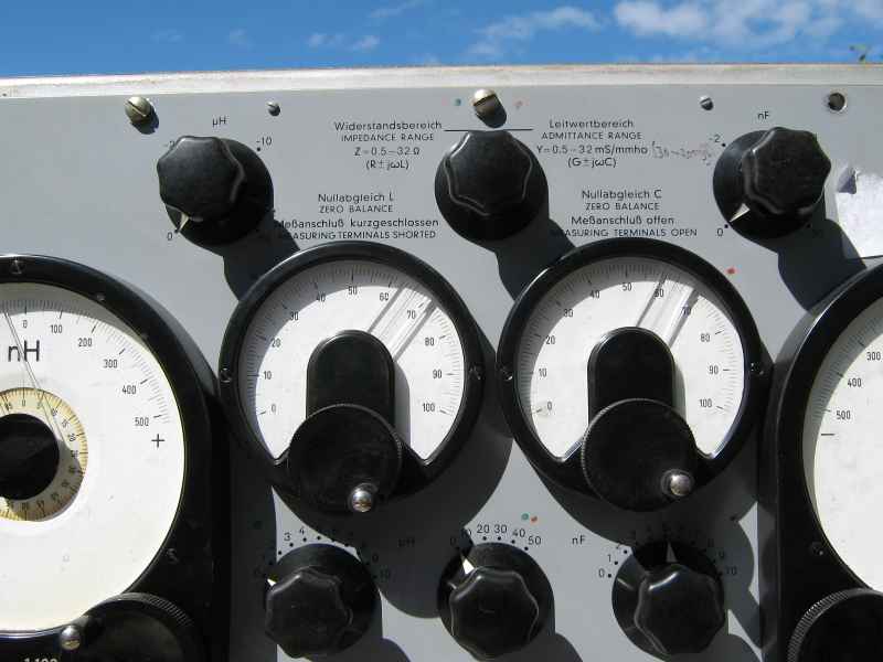
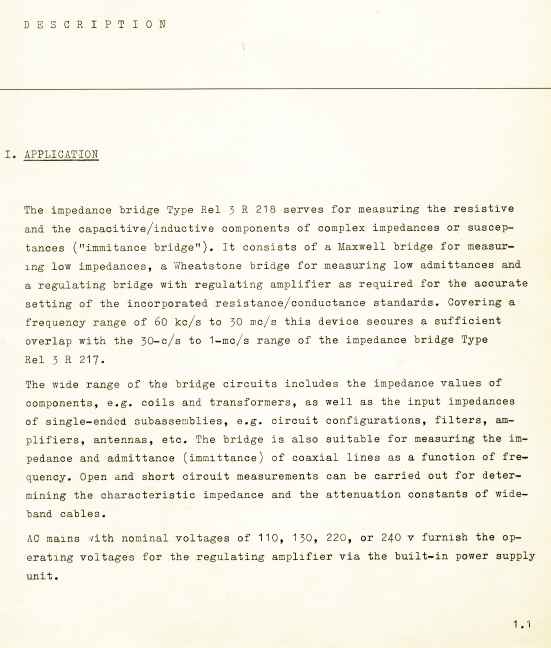
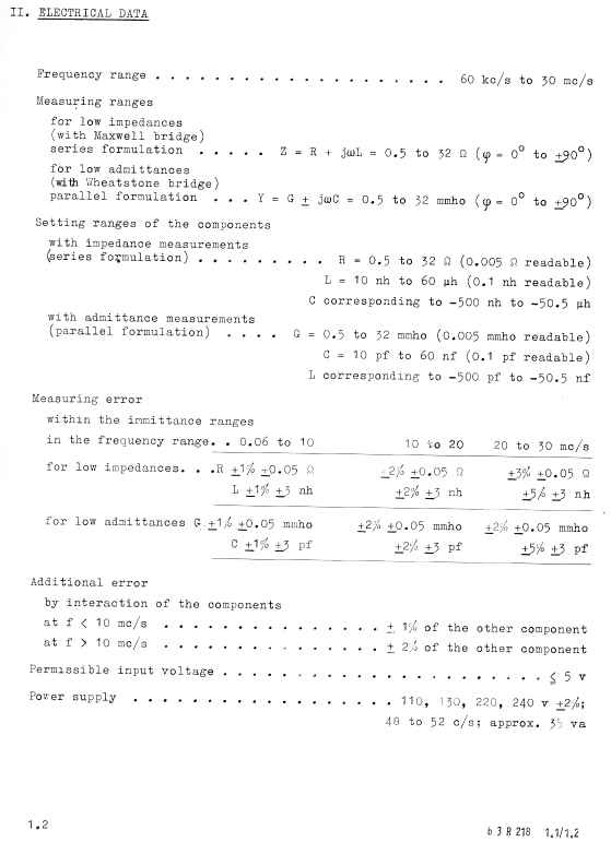
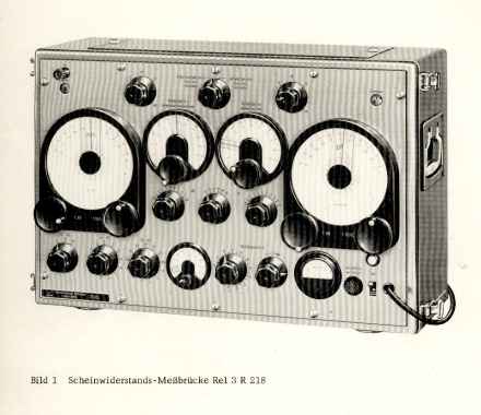
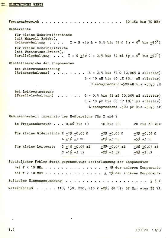
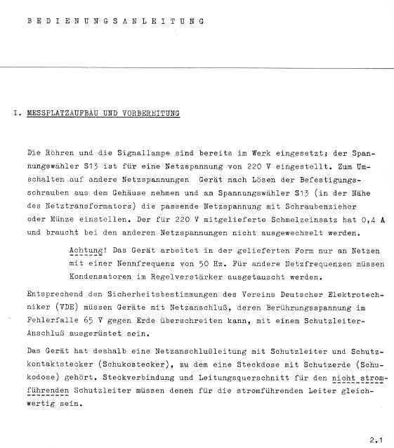
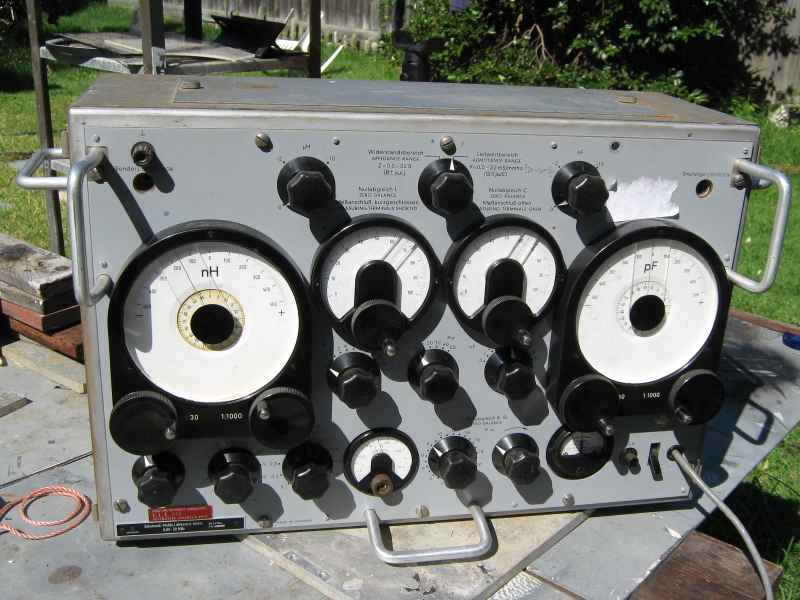
The Siemens R218 impedance bridge is a precision instrument for measuring complex impedance and admittance in two separate bridge mechanisms covering 60khz to 30Mhz.
This remarkable unit was purchased by me at the recent EMDRC Hamfest. I have seen this unit on sale at other hamfests but there were no takers. It looks expensive, once upton a time it actually was expensive, very expensive indeed. I raised the courage to ask the price. Only $20 ! I bit the bait. Maybe I should have been more circumspect and checked whether or not I could even lift this object. No, I could barely budge it, much less heave it back to the car. Adam, VK3FAFP generously helped me haul it to my car.
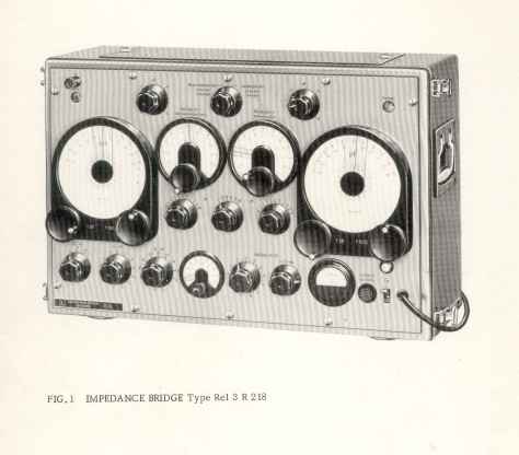
I was intrigued by this device. It looked like it belonged inside a German U-Boat. Given that it was manufactured in the early 1960s it actually may have been designed by the same people that had made U-Boats !
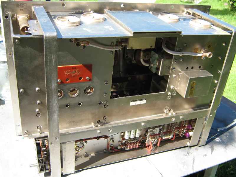
I finally got this unit home and onto my outdoor bench which has the space to open this thing up. It weighs in at an astonishing 38 kgs !
Why so much ? Its just a piece of electronic test equipment !
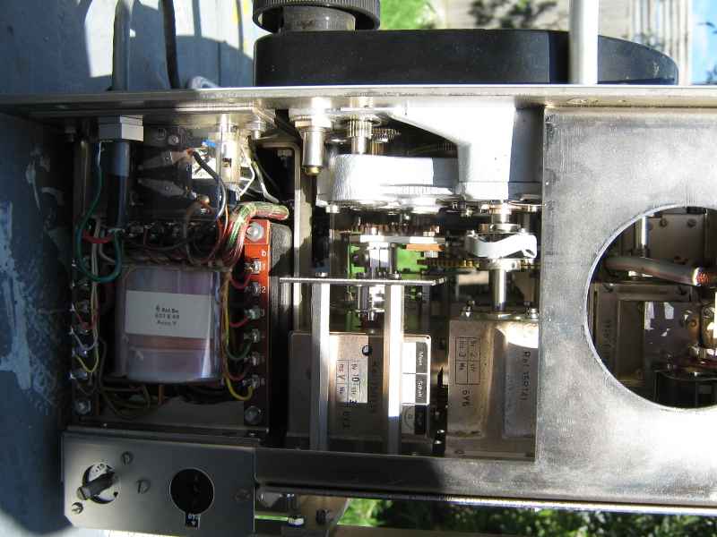
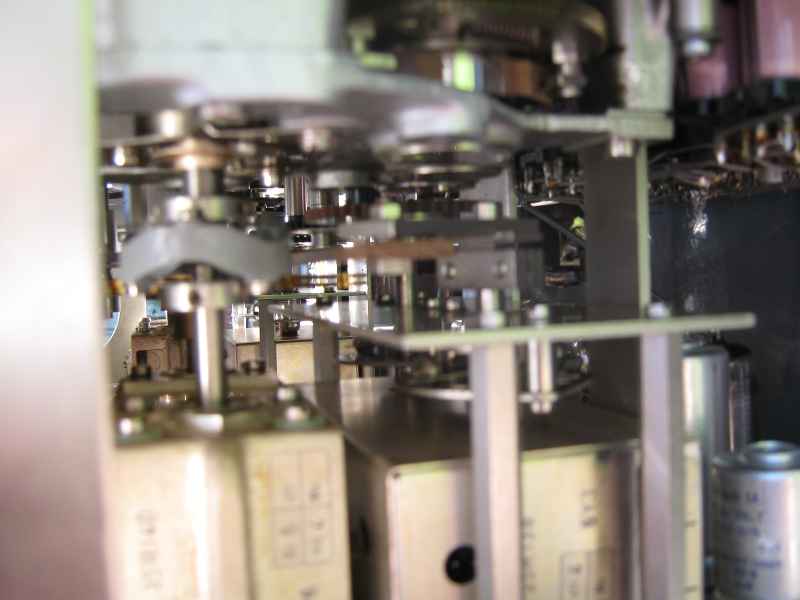
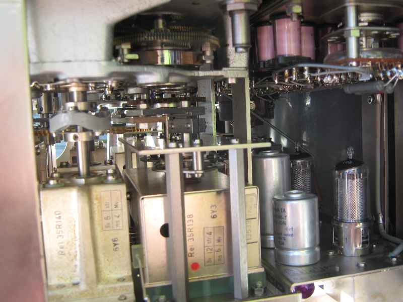
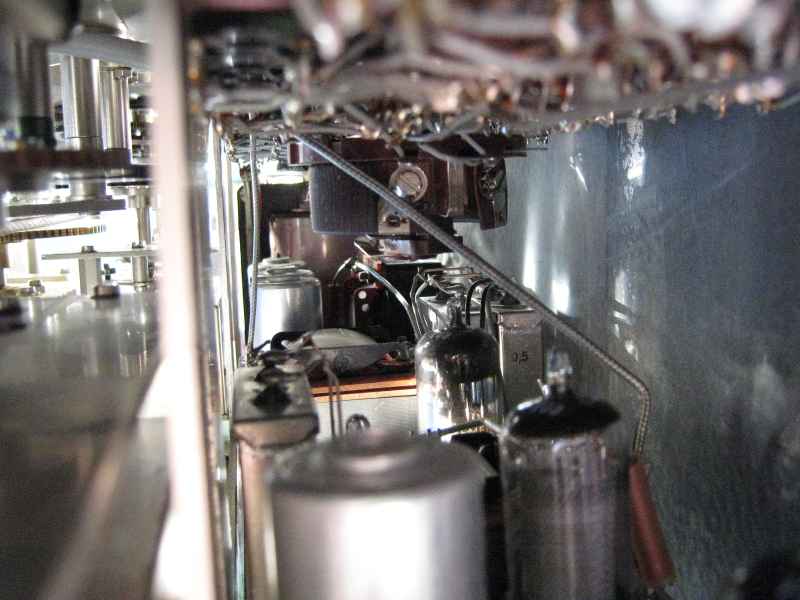
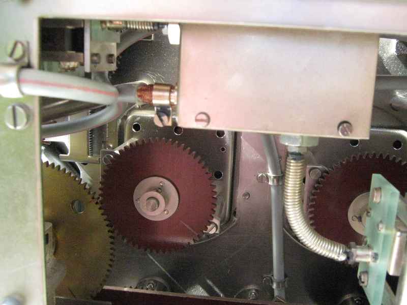
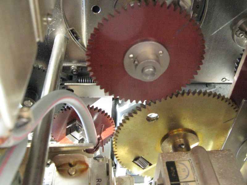
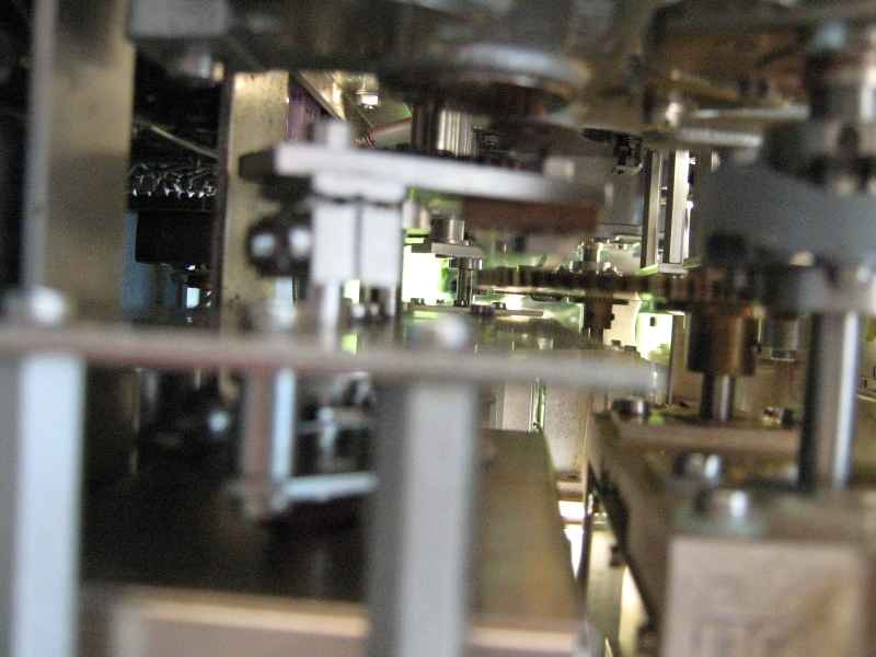
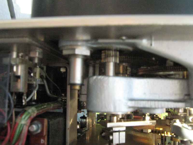
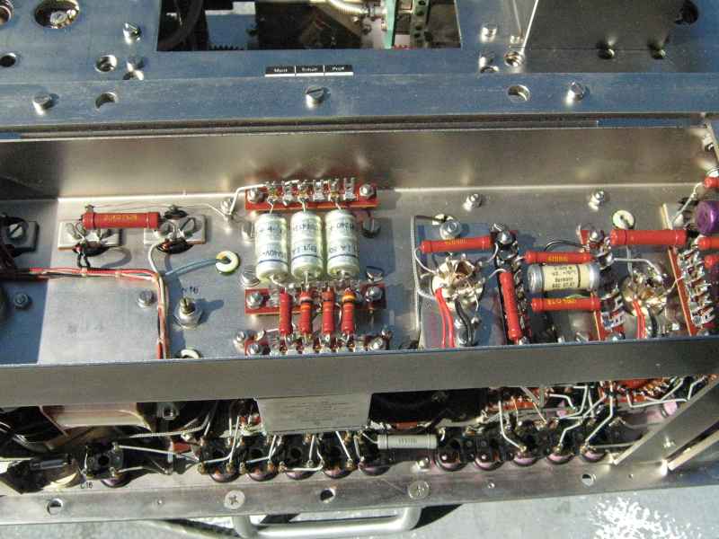
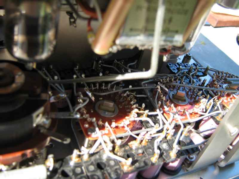
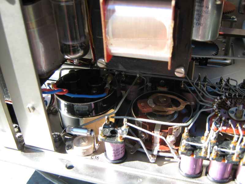
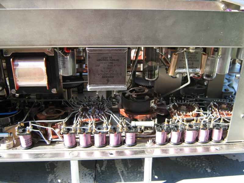
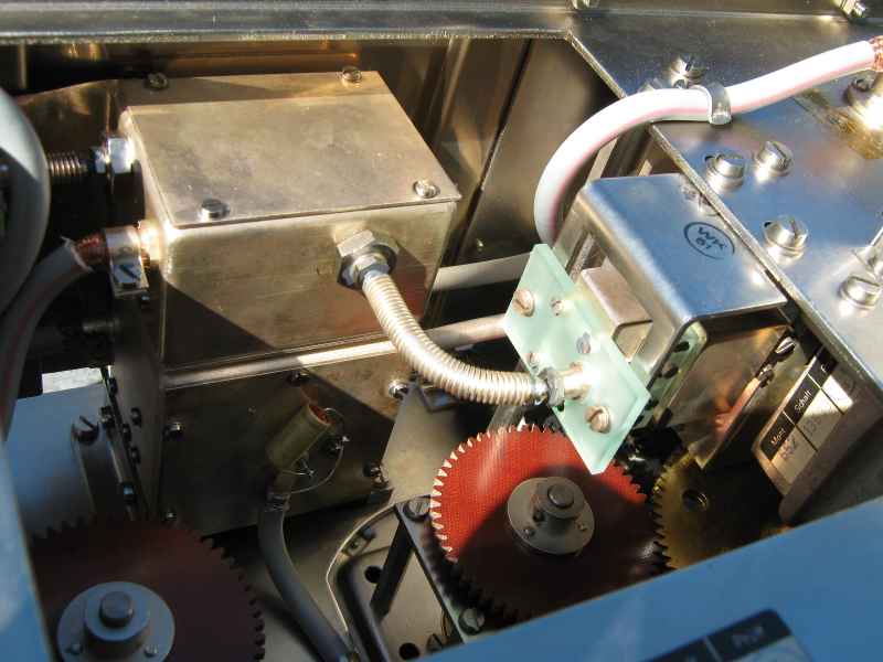
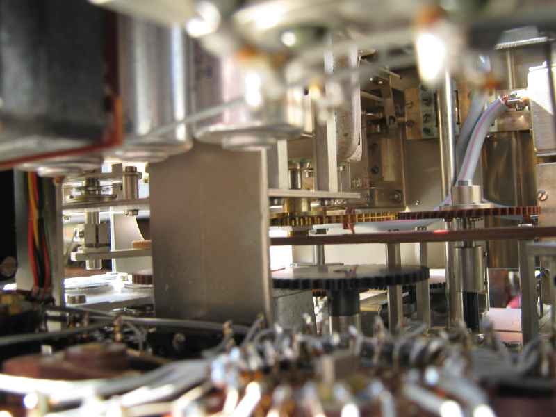
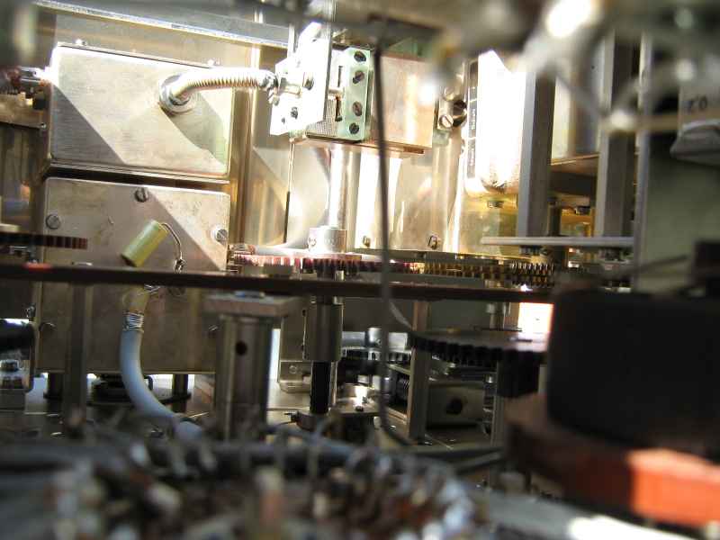
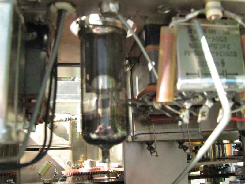
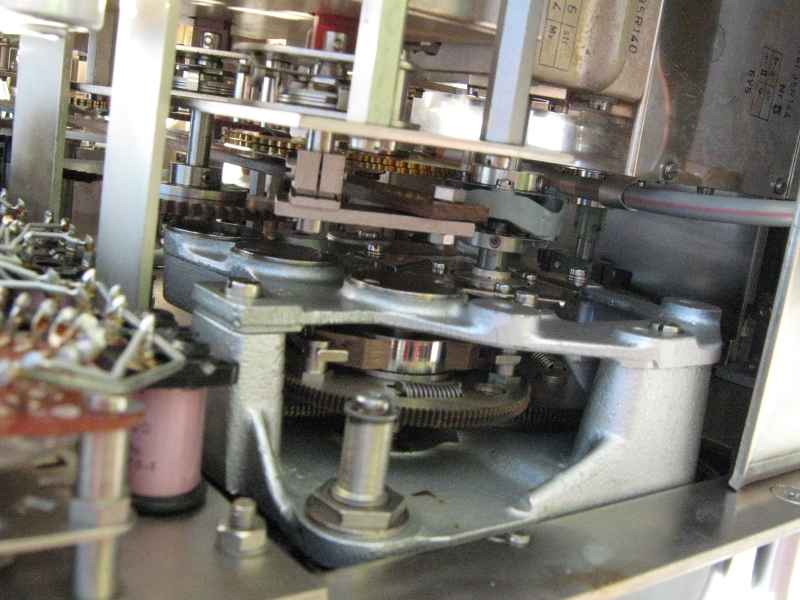
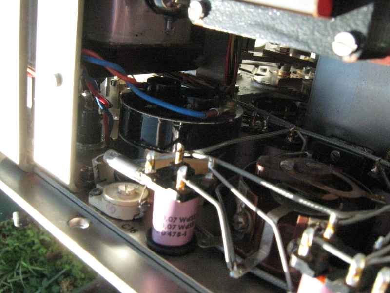
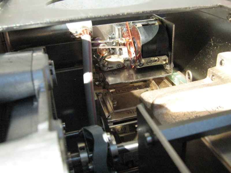
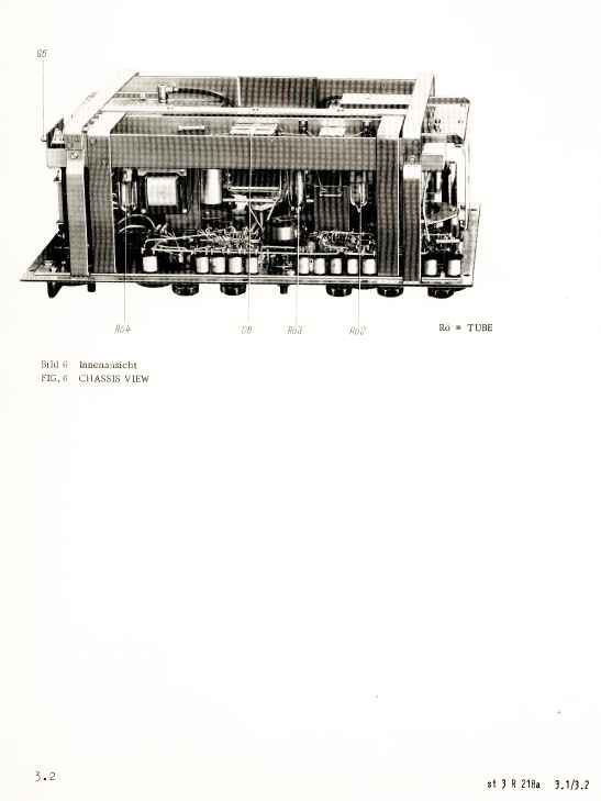
When I opened up the case, I was greeted with the same smell that greeted my when I first opened up my British Army Larkspur radios. It smelled OFFICIAL ! I was 15 years old when I had first bought and opened up a British Army Larkspur radio and gazed in awe and wonder at the sheer mind boggling complexity. This same sense of awe was upon me once again. The interior of the R218 Bridge is a magnificence of German precision engineering and pride in workmanship. It is an intricate maze of clockwork that brings the front panel controls to the controlled variable devices and switches. It is all heavy castings, brass gears, sealed metal boxes that hide their trade secrets and high purpose.
I have noted that this unit was expensive. It had been purchased by the ancestor of Telstra, the Australian Post-Master-Generals Department in the early 1960s for some unfathomable purpose. They had purchased the Rolls-Royce version. I am sure that something cheaper would have been appropriate. It is clear from the condition of the device that it had only barely been used. Given its eye watering cost they would not have let field personel near it. It must have sat in their research lab for years pretty much unused until disposal.
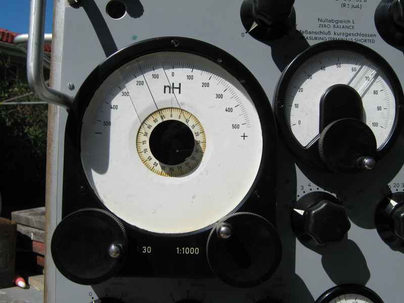
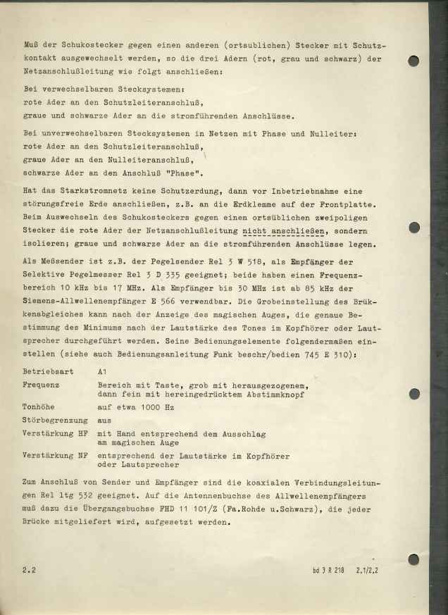
The best part of all was that this device came with the BOOK ! I have the manual ! Just as well . Operating the bridge is not intuitive.
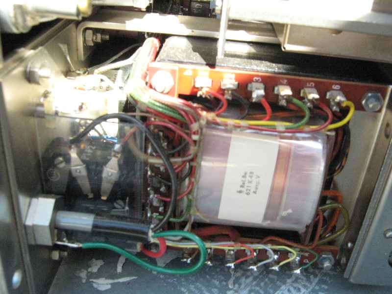
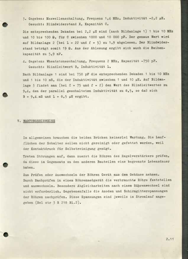
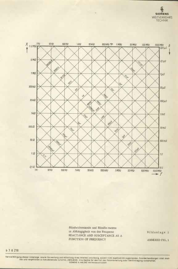
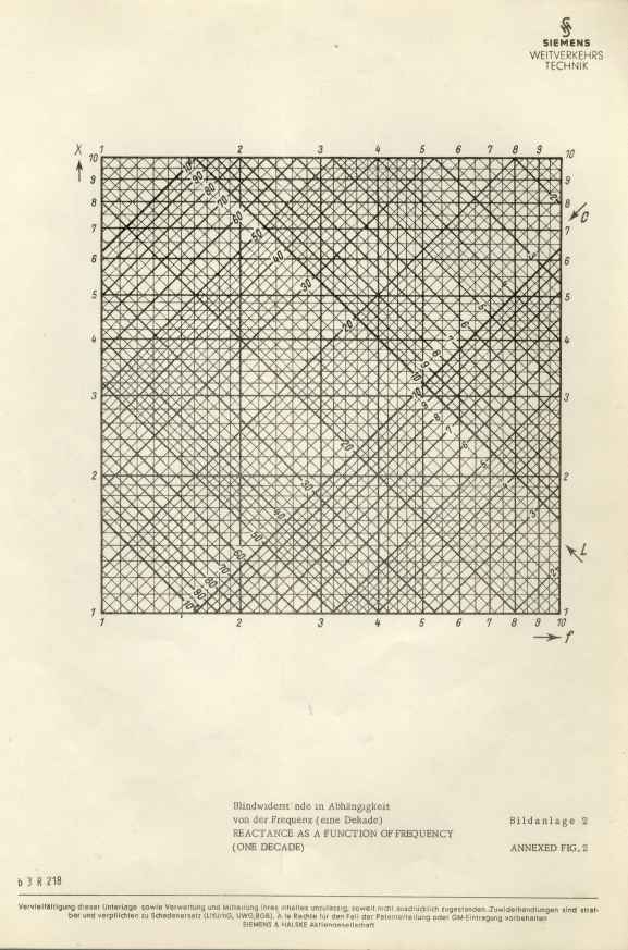
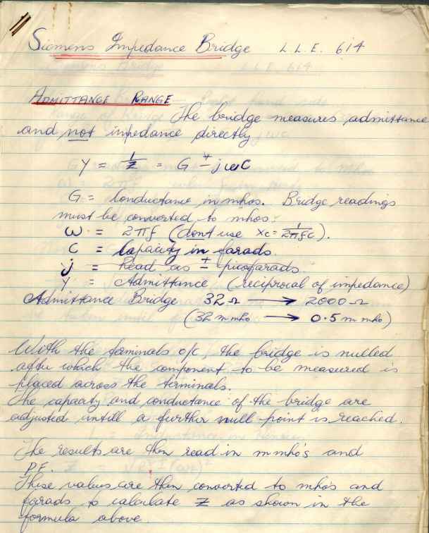
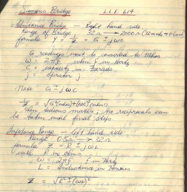
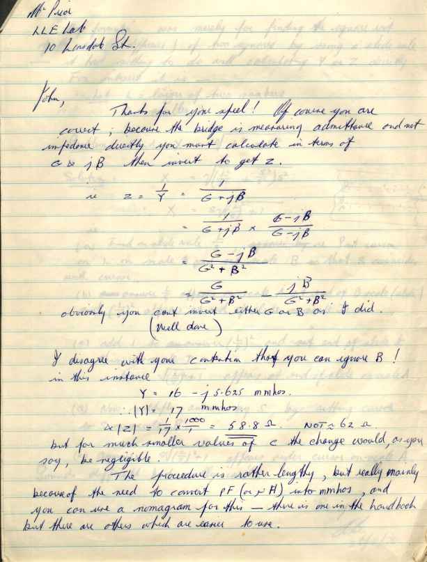
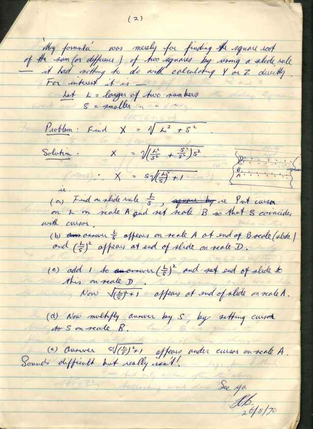
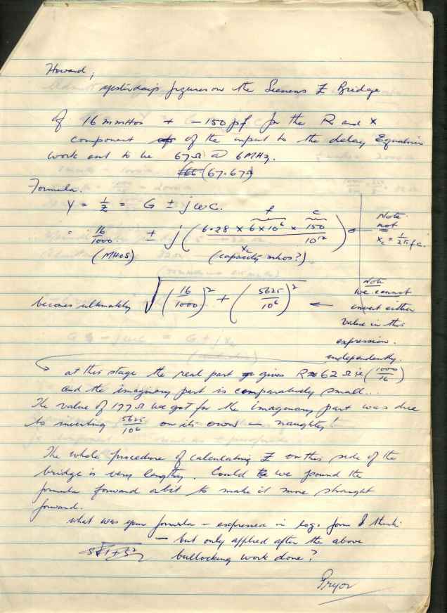
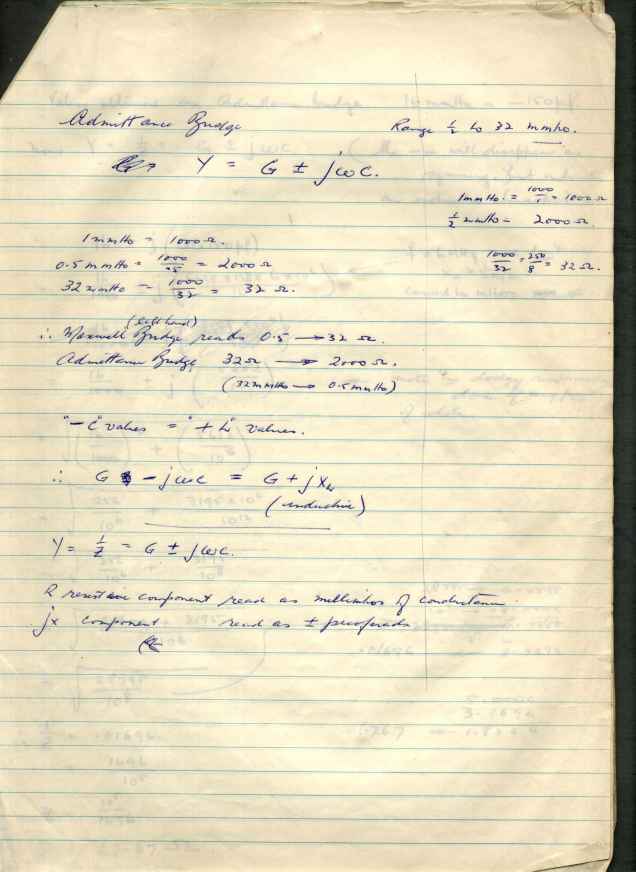
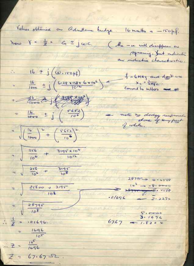
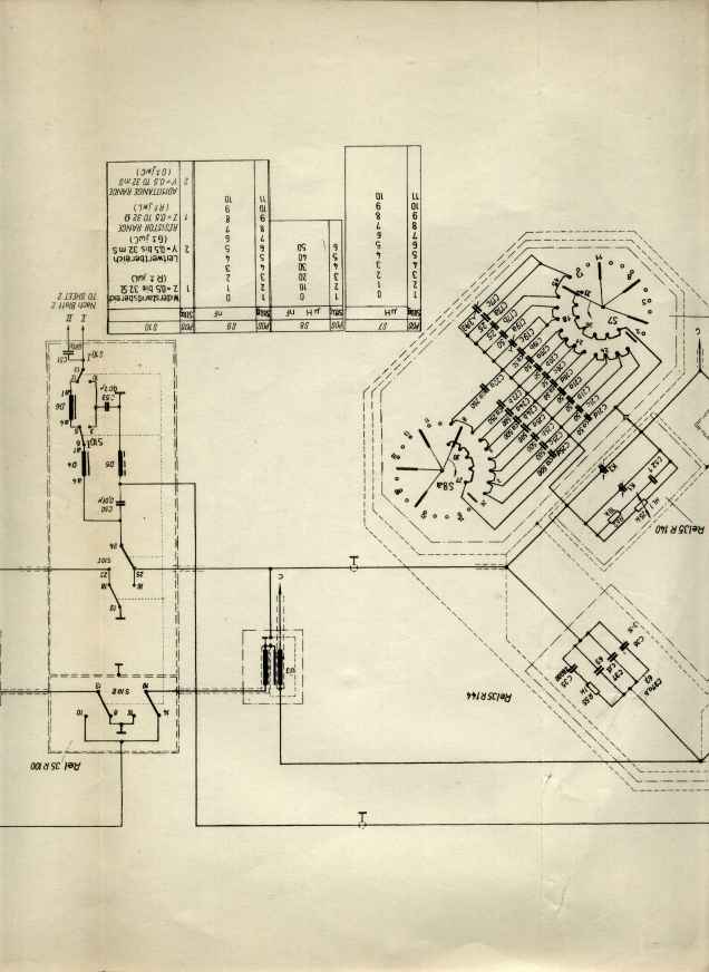
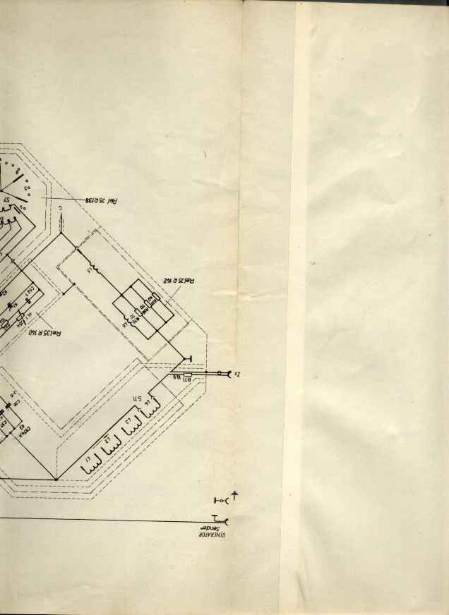
The real item of antiquarian interest is that the BOOK contained usage notes dated 1970, written by one of their engineers who was trying to come to terms with using this unit. He recommends having a slide-rule handy ! It is impossible to deduce the devices purpose design or circuit by examination due to its high component density and mechanical complexity. The business parts of the bridge are contained inside sealed metal containers. The unit is progressively assembled making exploration or disassembly extremely challeging . It was built with laboratory grade components, better than mil-spec, with the clear intention that repair should never be required.
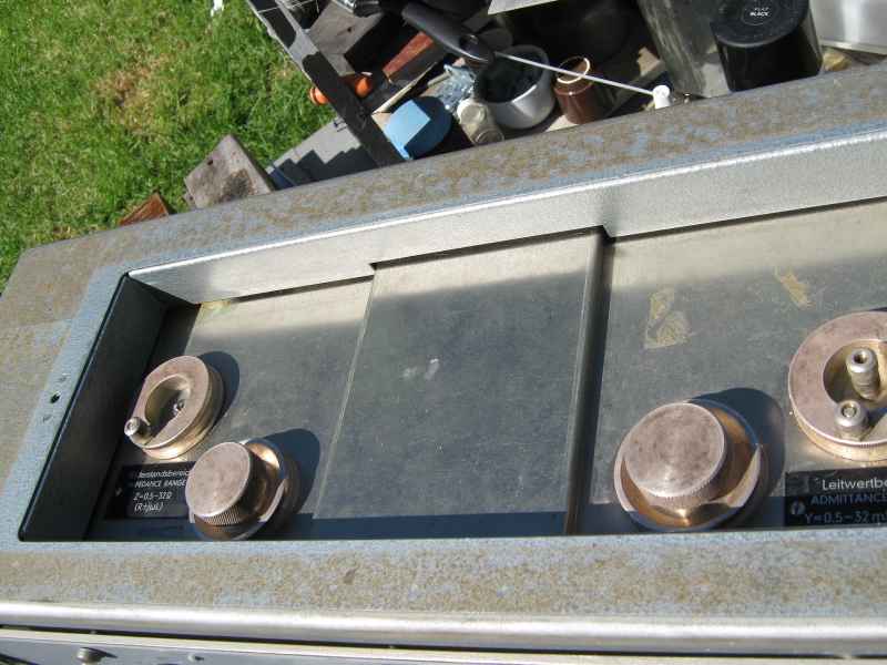
The best way to open this unit is to stand it upright with ample bench space in front. Remove the screws holding it into the case. Slide the unit forward. It has internal slides on the base to permit this to happen. Do not attempt to lift it out with the case lying flat. Nearly all the weight ,38kgs, is in the unit, not in the case which is only a couple kg. Make sure that all test terminal connectors from the top of the unit have been removed. The case is notched to permit the unit top terminals to simply slide out. Caution; they are only 3mm brass tapped posts and are fragile and would be extremely difficult to replace.
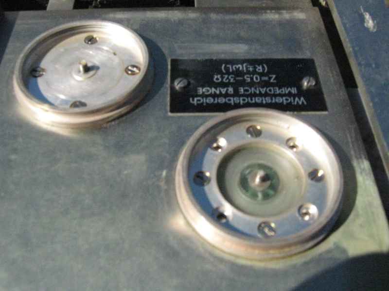
The generator and detector ports use a funny Siemens proprietery coaxial connector. Unless you can find these , you may have to improvise. This wount be a problem, this part of the circuit is not sensibly sensitive to impedance, so that any decent BNC connectors will do.
My observations about the theory of operation.
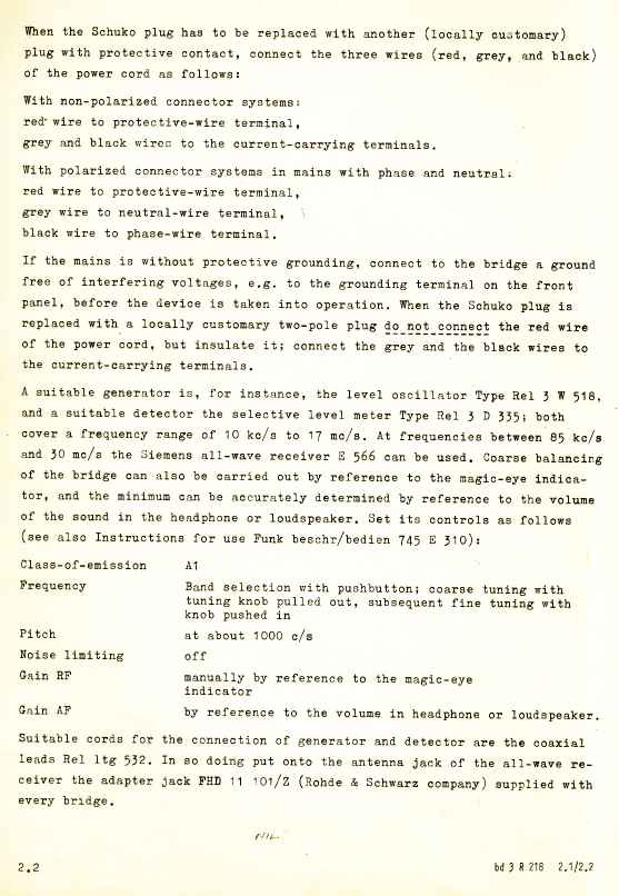
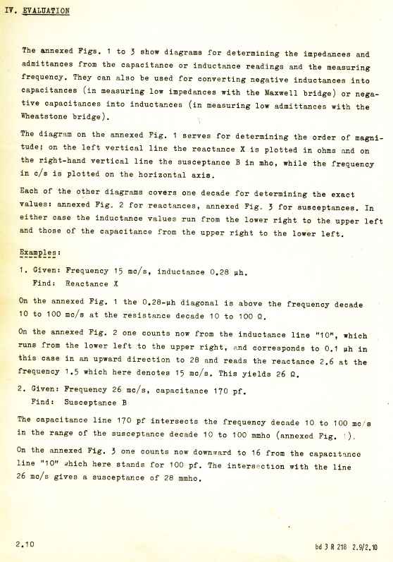
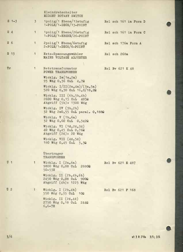
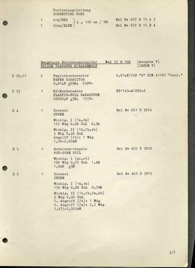
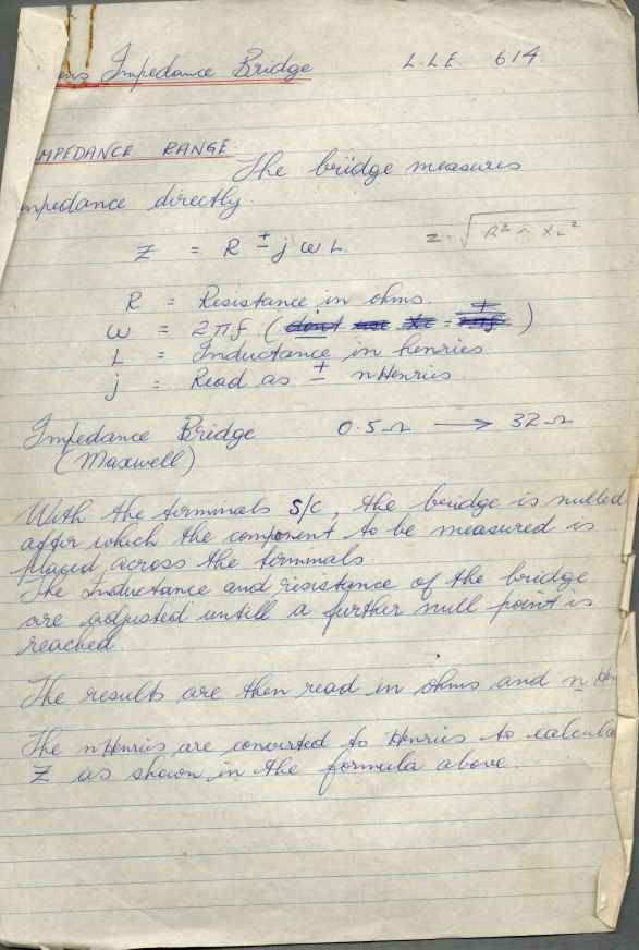
The manual has a brief writeup in English about how it works, and a detailed design description in German.
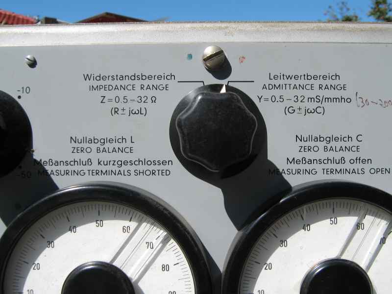
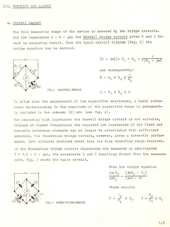
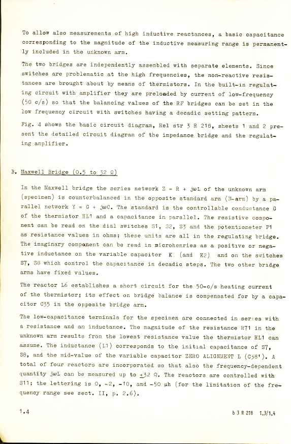
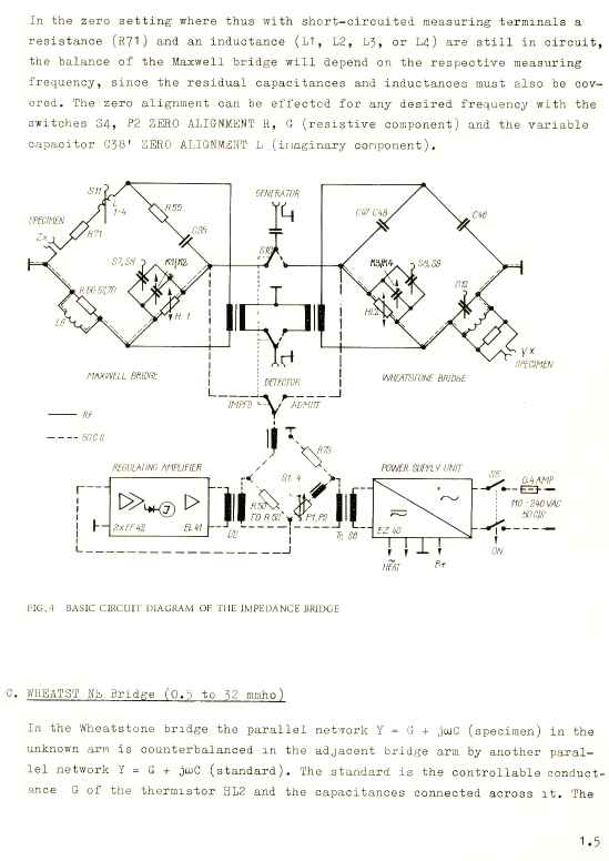
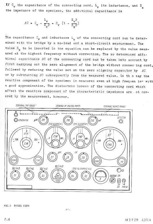
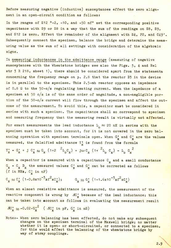
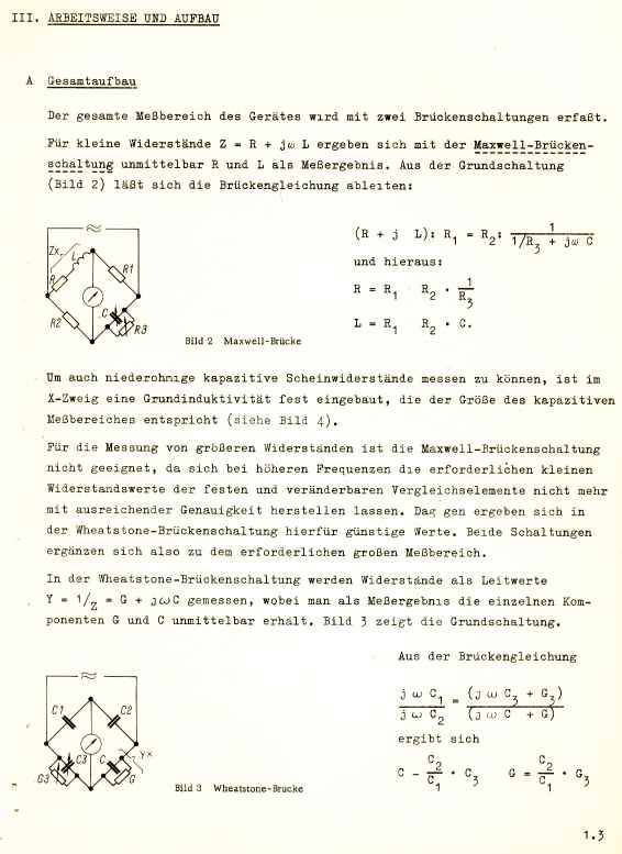
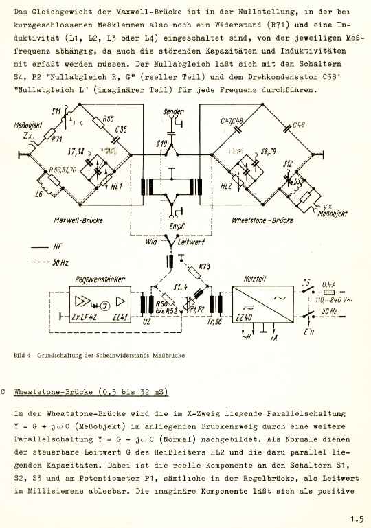
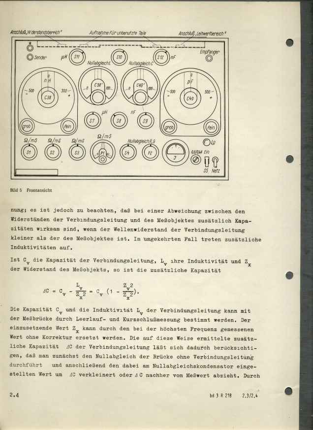
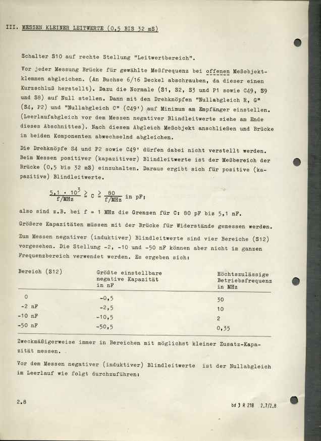
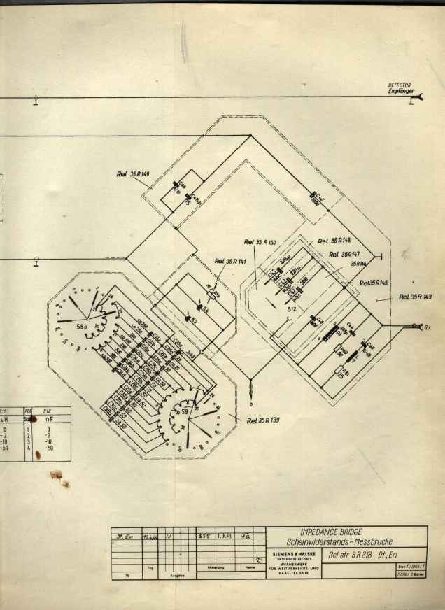
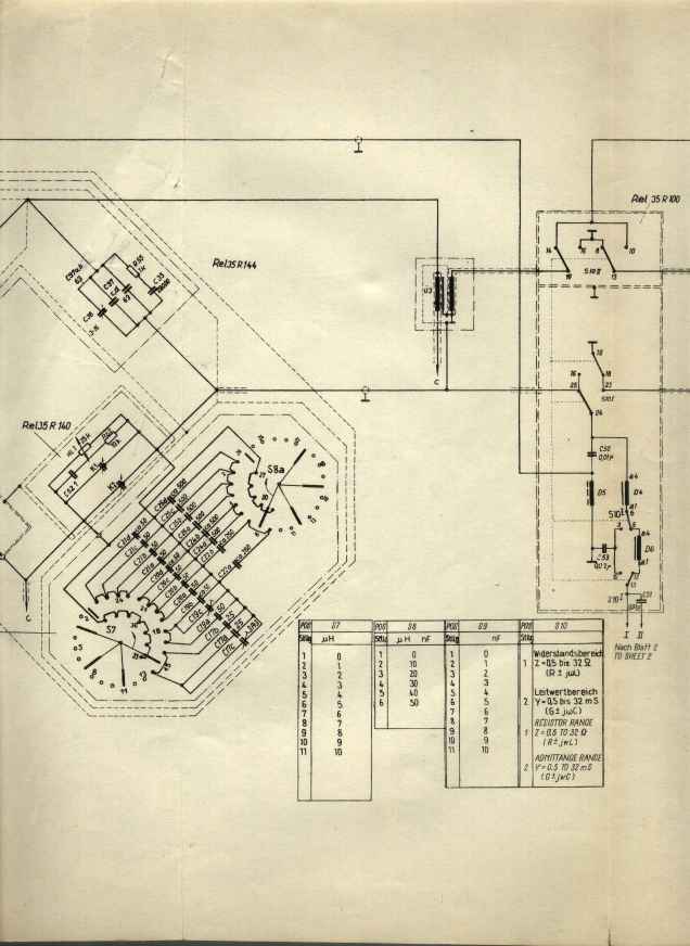
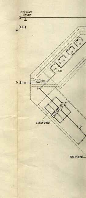
The bridge has two component bridges, a Maxwell bridge for impedance measurements and a Wheatstone bridge for admitance. Both have differant scopes. Impedance of low magnitude Z is best done with a Maxwell Bridge. High magnitude impedance is best measured with an admittance bridge. The test ports are brought out to separate terminals for each bridge.
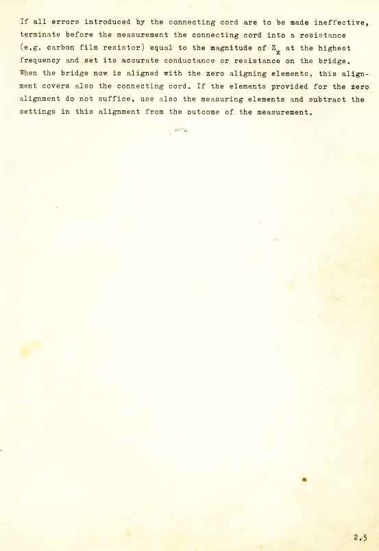
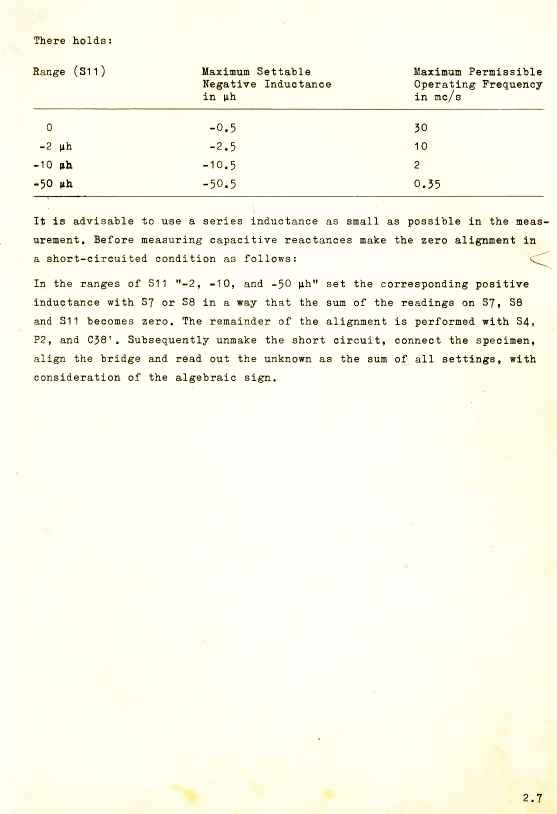
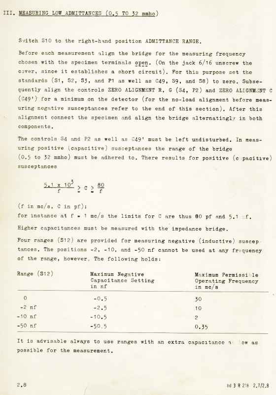
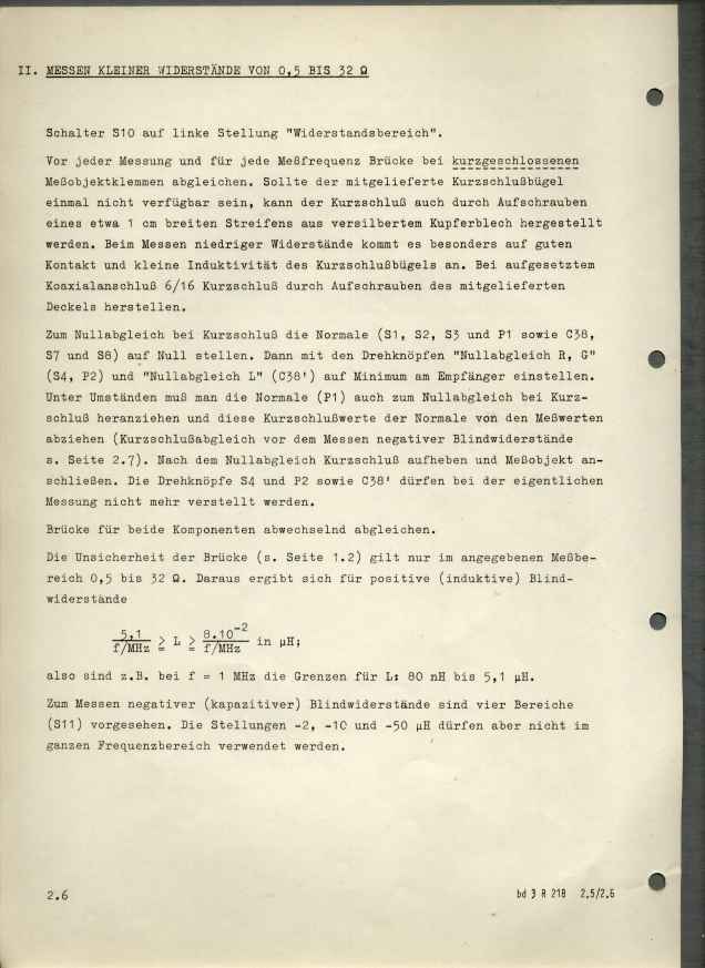
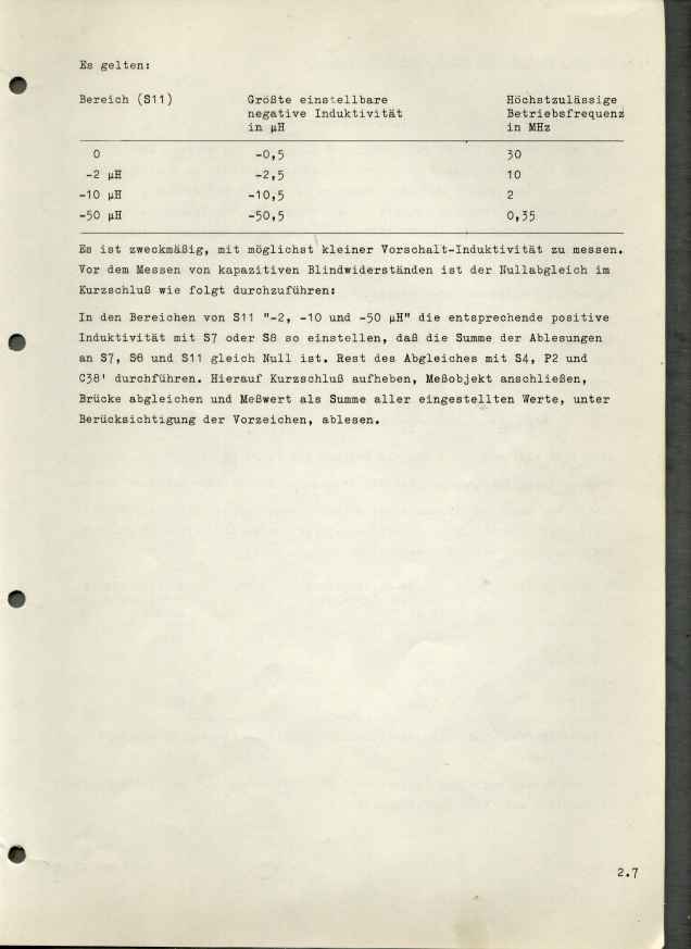
The bridge is first zero calibrated with the test short circuits. The measurement is then made on the device-under-test using an external signal source and an radio external detector.
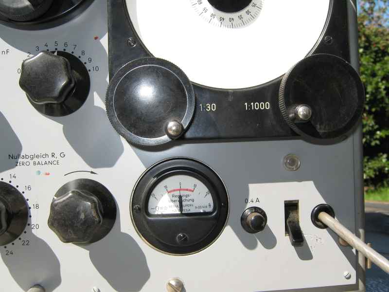
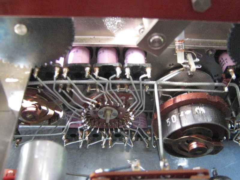
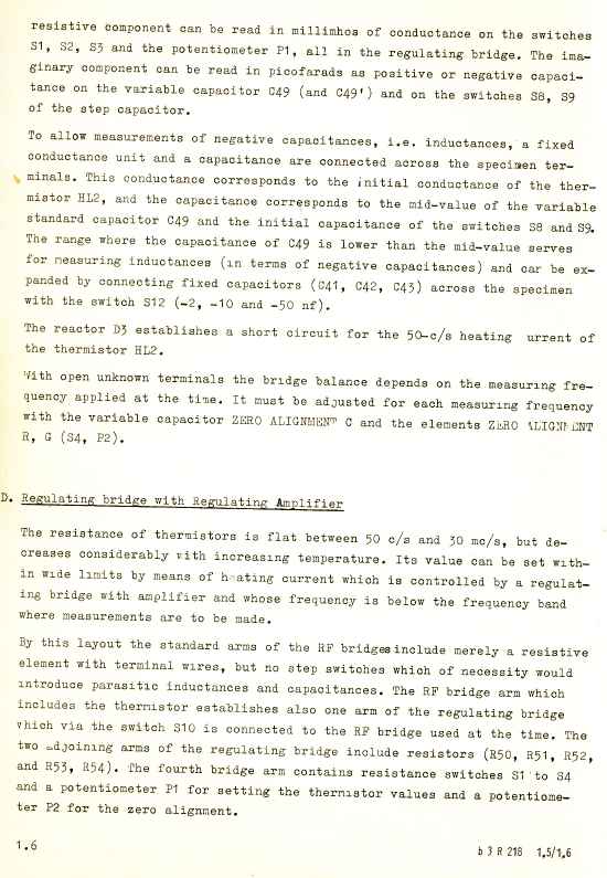
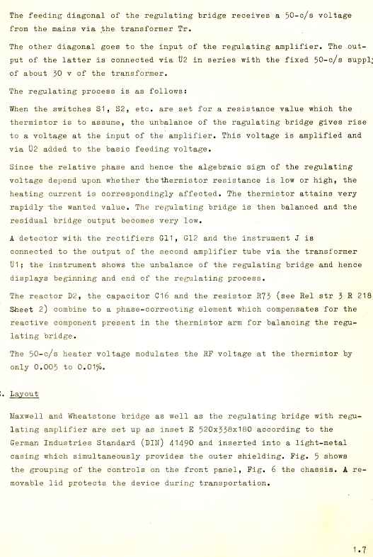
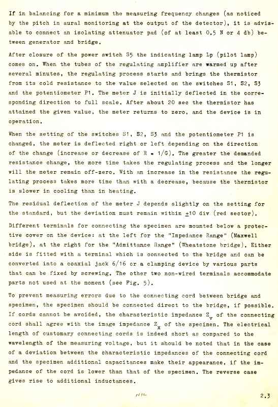
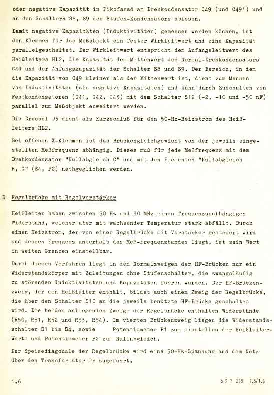
The bridge is brought to balance internally with variable capacitance elements for the Complex Z or Y. The Real part of Z or Y is balanced by a variable resistor. Now this part is stunning. A variable resistor, a "pot" is a mechanical component of very uncertain calibration and a complex impedance that is not "canonical". The R218 uses a "pure" resistor. Only it is not a resistor, it uses a thermistor to balance the bridge. The thermistor is heated to change its resistance is response to the front panel controls. The user thinks he is turning a pot. Not so. The front panel resistance arm controls are made from precision wire wound resistors. There is an internal Wheatstone bridge based servo that makes the thermistor track , exactly, the resistance assembled from a switched network of wirewound references. This is done by modulating a 50Hz supply that is transformer coupled to the thermistor but is still isolated by chokes from the measurement path. The thermistor has a range from low ohms to about a kilo ohm. Its AC impedance reactance does not sensibly change over this range and the measurement path does not have to traverse an uncertain network of switches and pots. The design is ingenious. Its the sort of "alien artifact" design that HP used to do at this time in the 1960s.
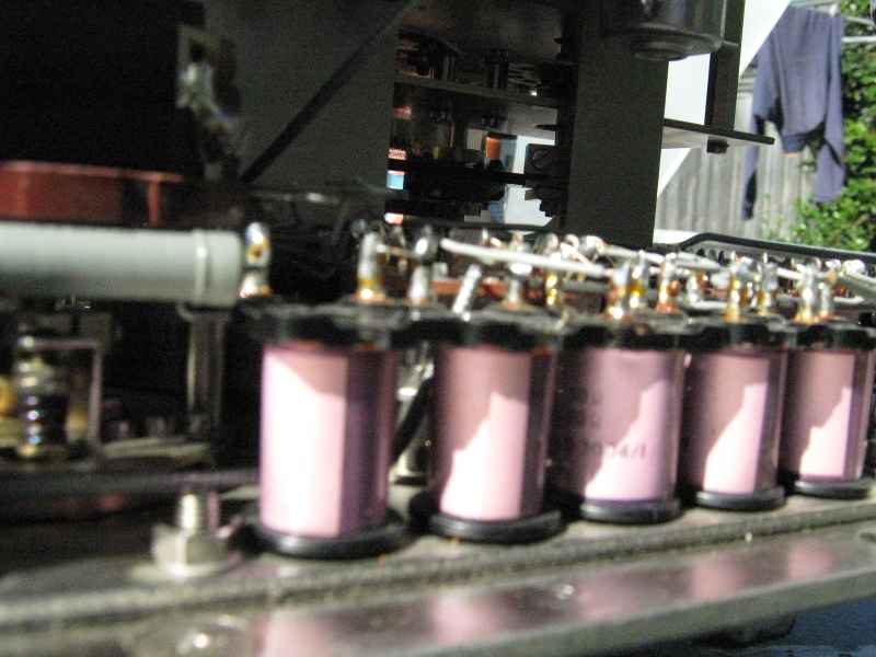
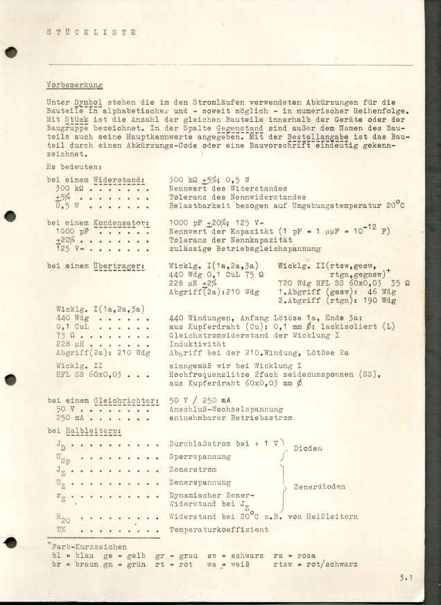
The resistance standards are true standard resistors. They are all "wickles" or wirewould resistors. Not the kind we are accustomed to. When Siemens made a precision resistor they wound a calculated length of fine wire on a spool and called it a resistor!
The fact that it has a significant inductance is not an issue here because only the "dc" component of the thermistor resistance
is measured by an internal servo bridge to the actual thermistor resistance which is made to track the front panel selection. Genius !
The design philosophy is contrasted to HP or General Radio (GenRad). With HP, the design philosophy of the 1960s was that mechanical complexity should be replaced by electronic complexity and as much as possible should be self calibrating through servo loops. GenRad , by contrast, relied on mechanical precision and complexity. The R218 is kind of a hybrid in this respect. I think half of their design team distrusted electronics and put their faith in precision and complex machinery. The thermistor control must have been quite a leap of faith on their part.

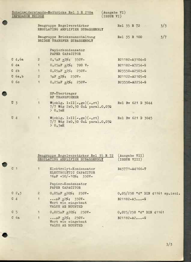
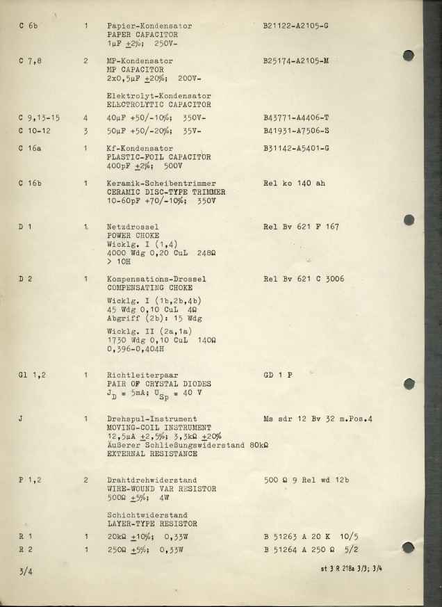
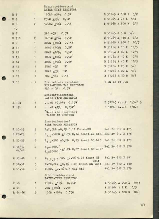
It
is type written. They cannot have sold many of these units.
I imagine that they would have built these only on receipt of an
order. Nothing about this device was cheap.
Mon Apr 16 12:22:39 AEST 2018 spelling, grammer, notes
