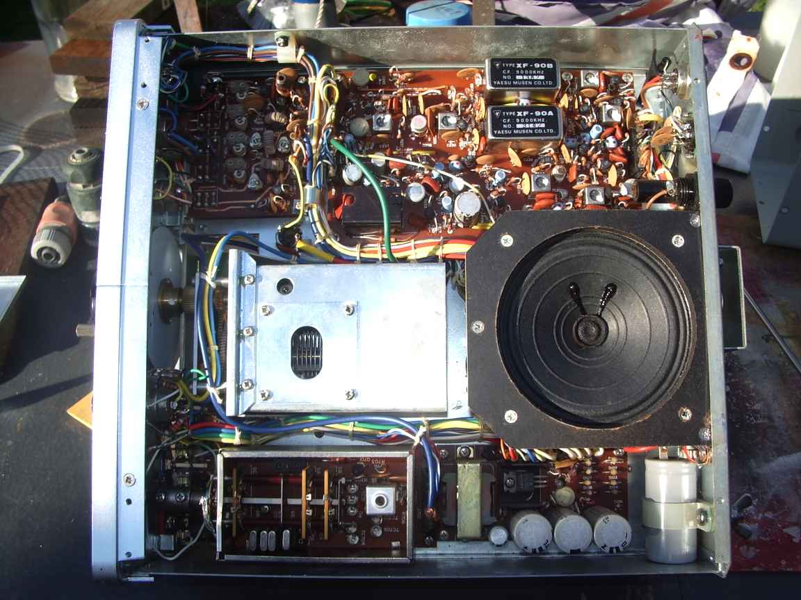
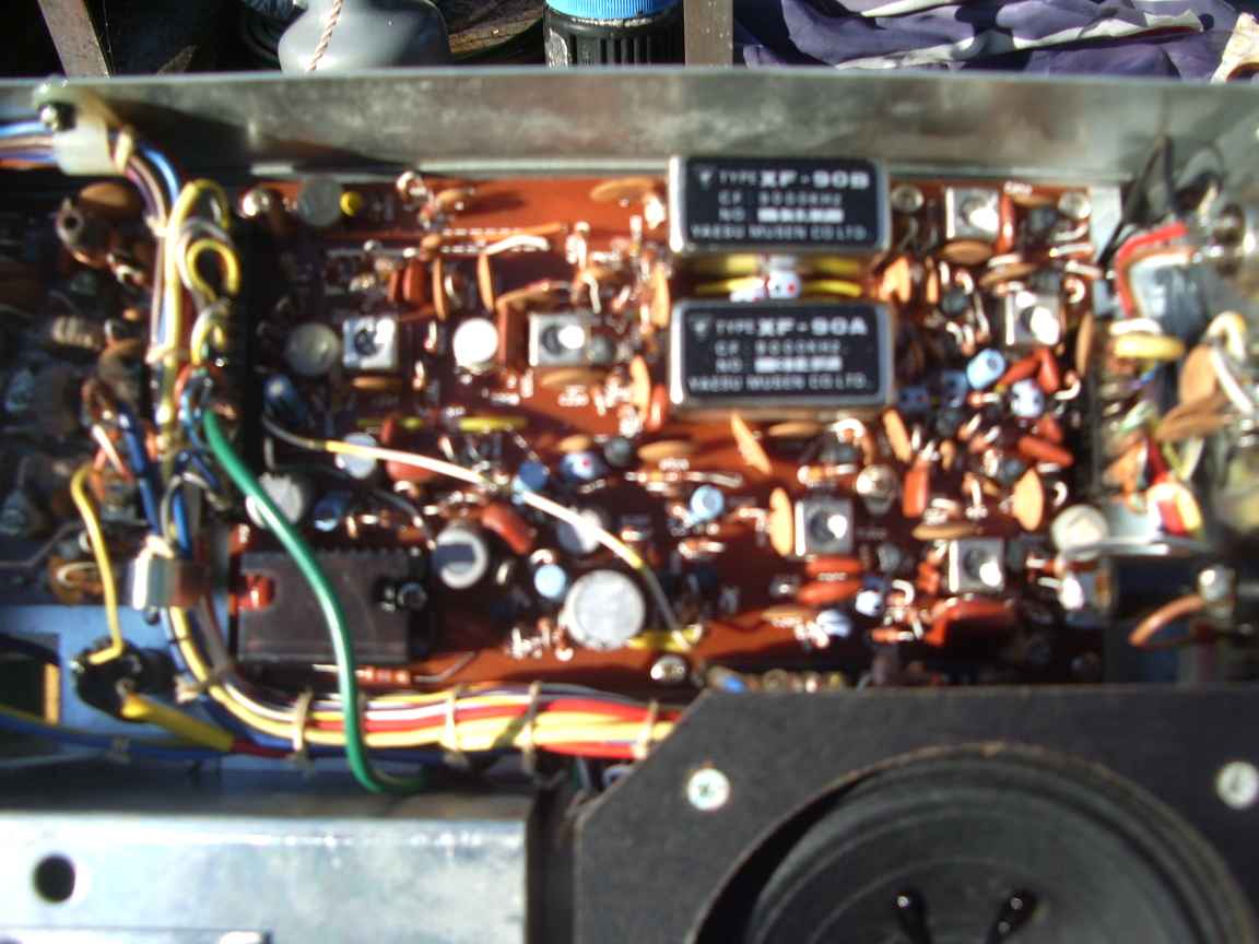
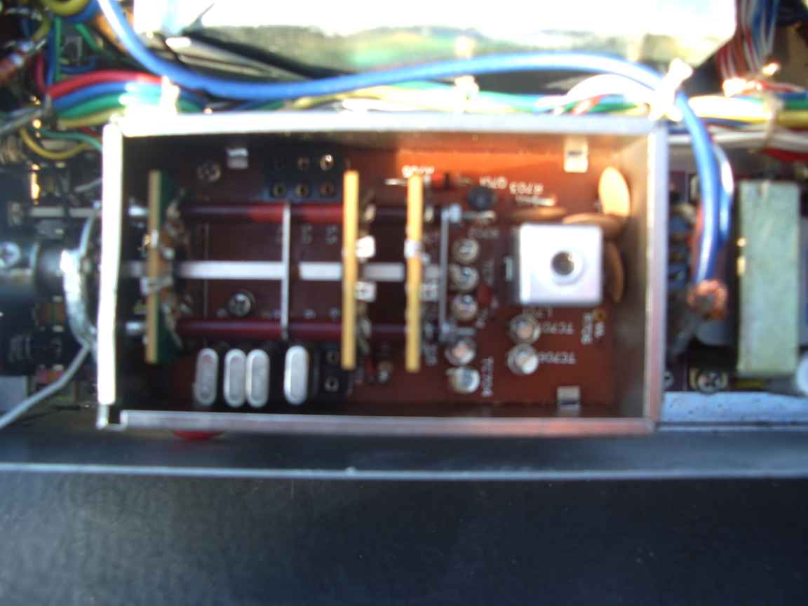
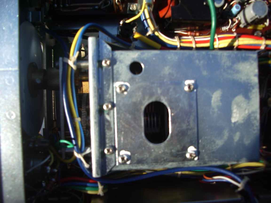
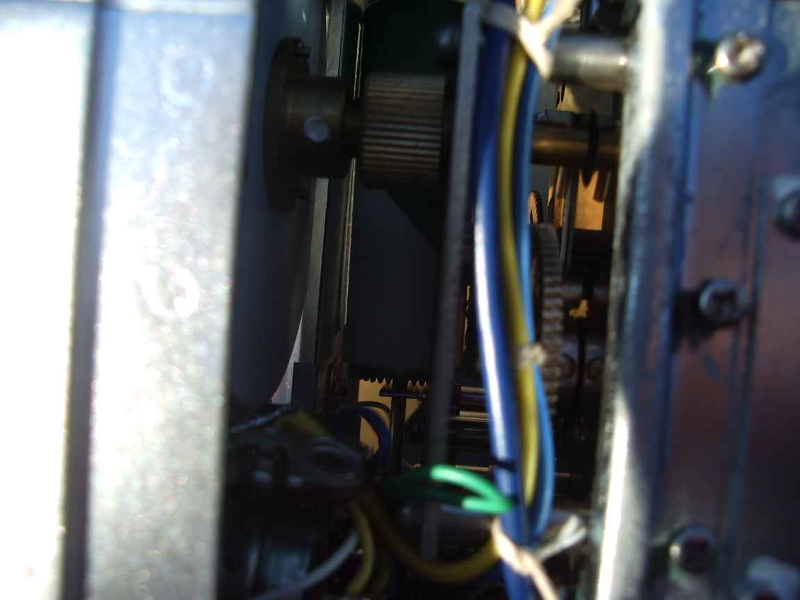
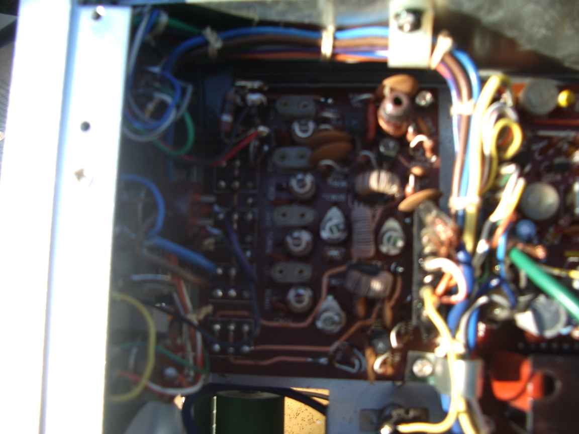
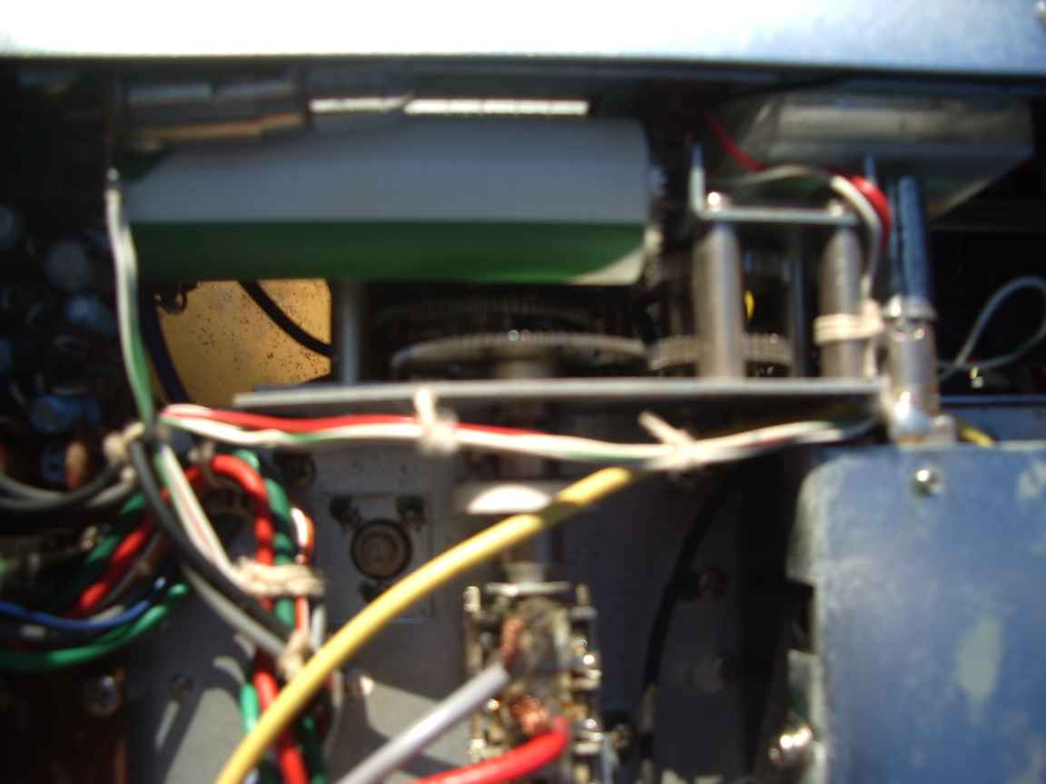
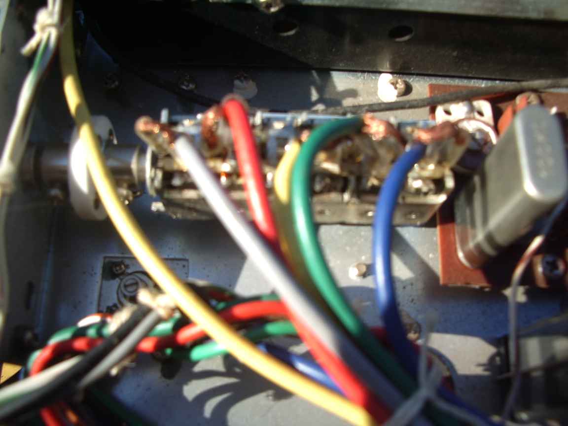
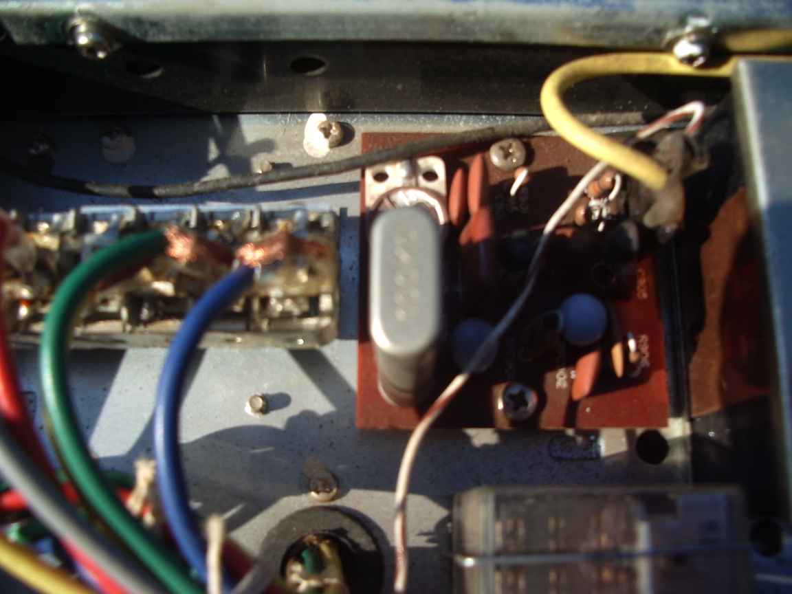
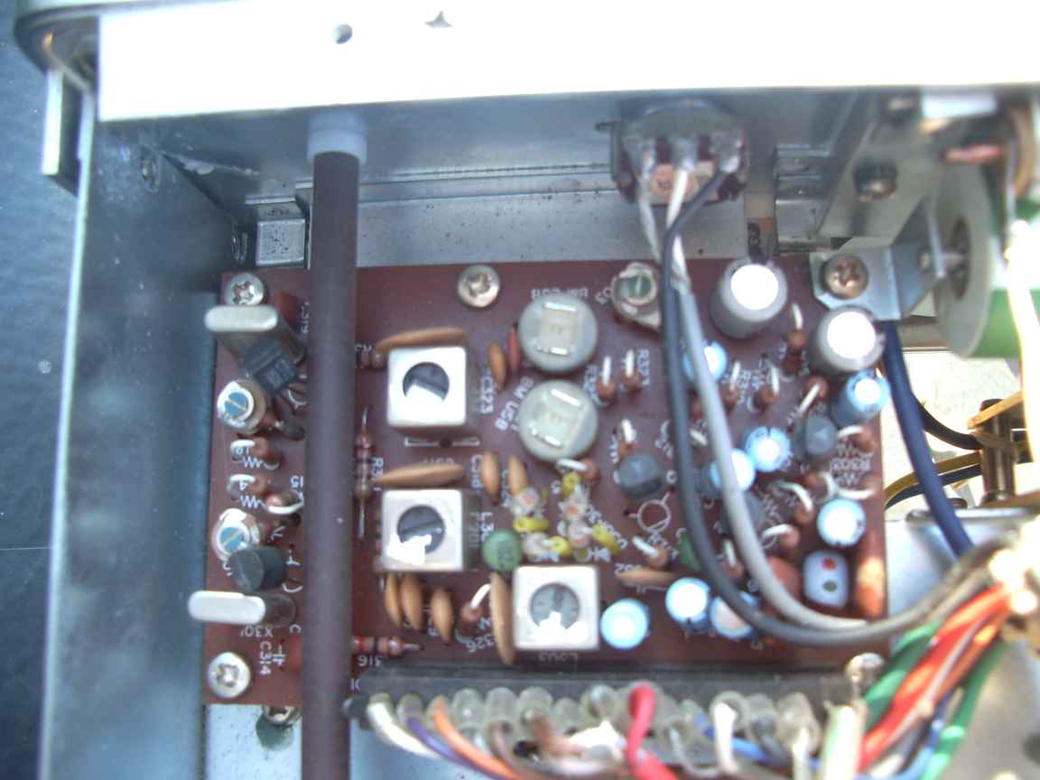
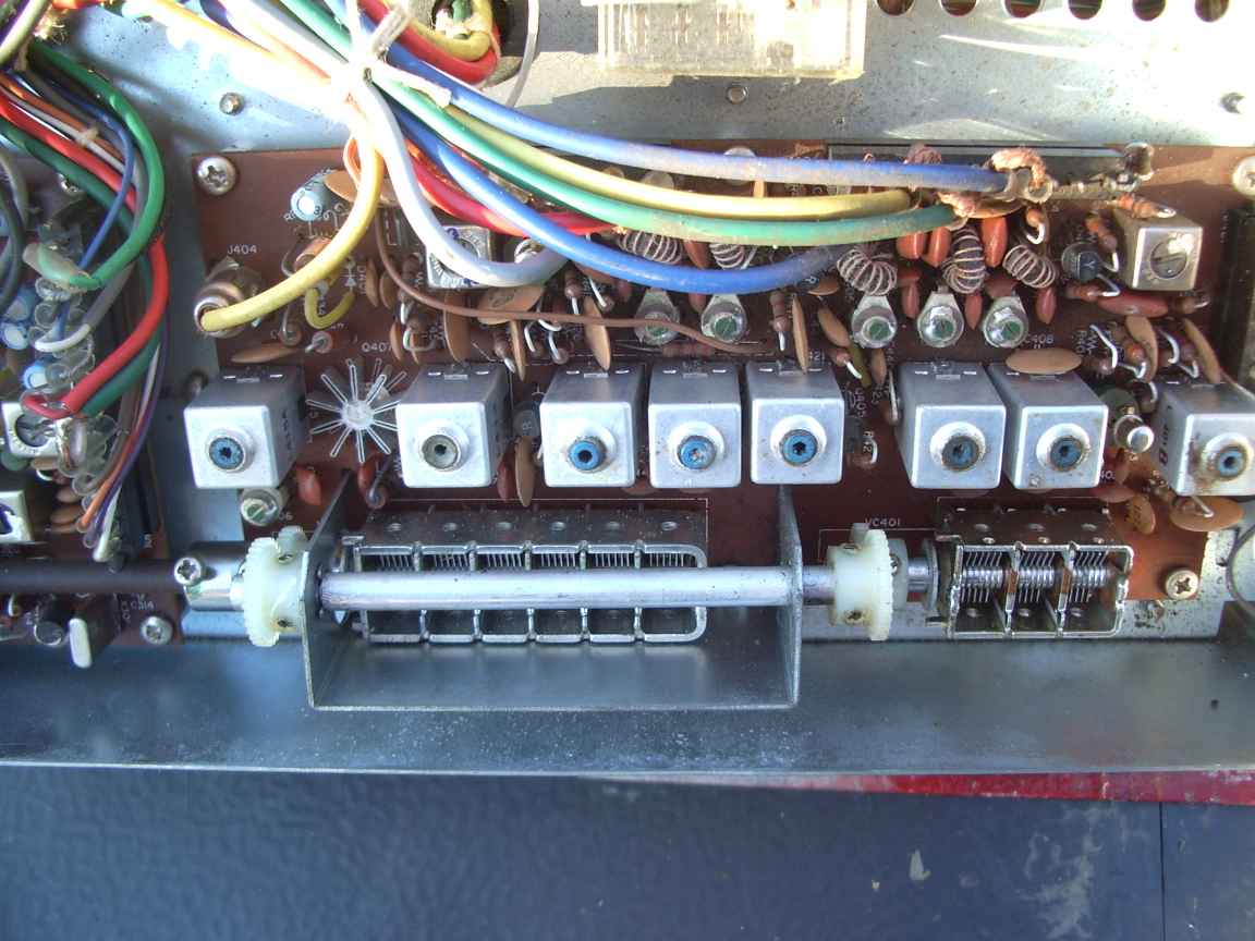
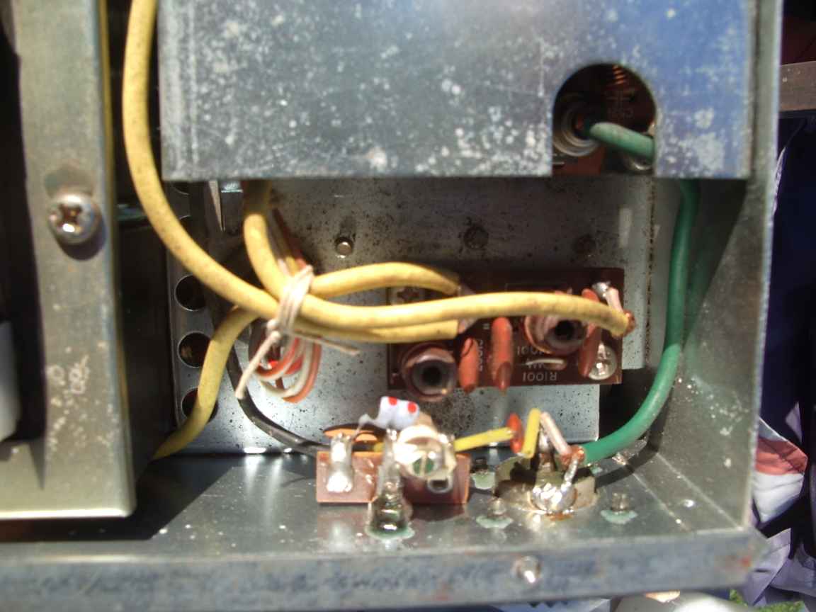
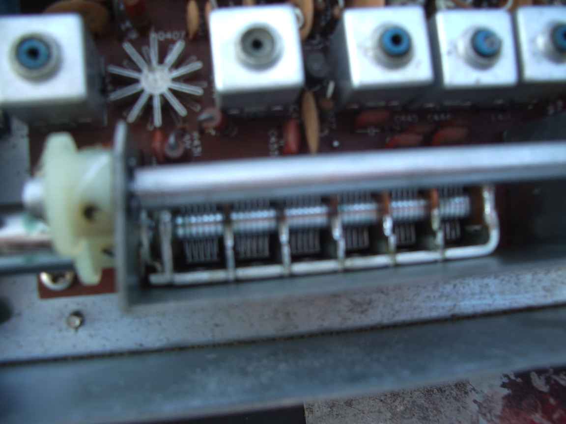
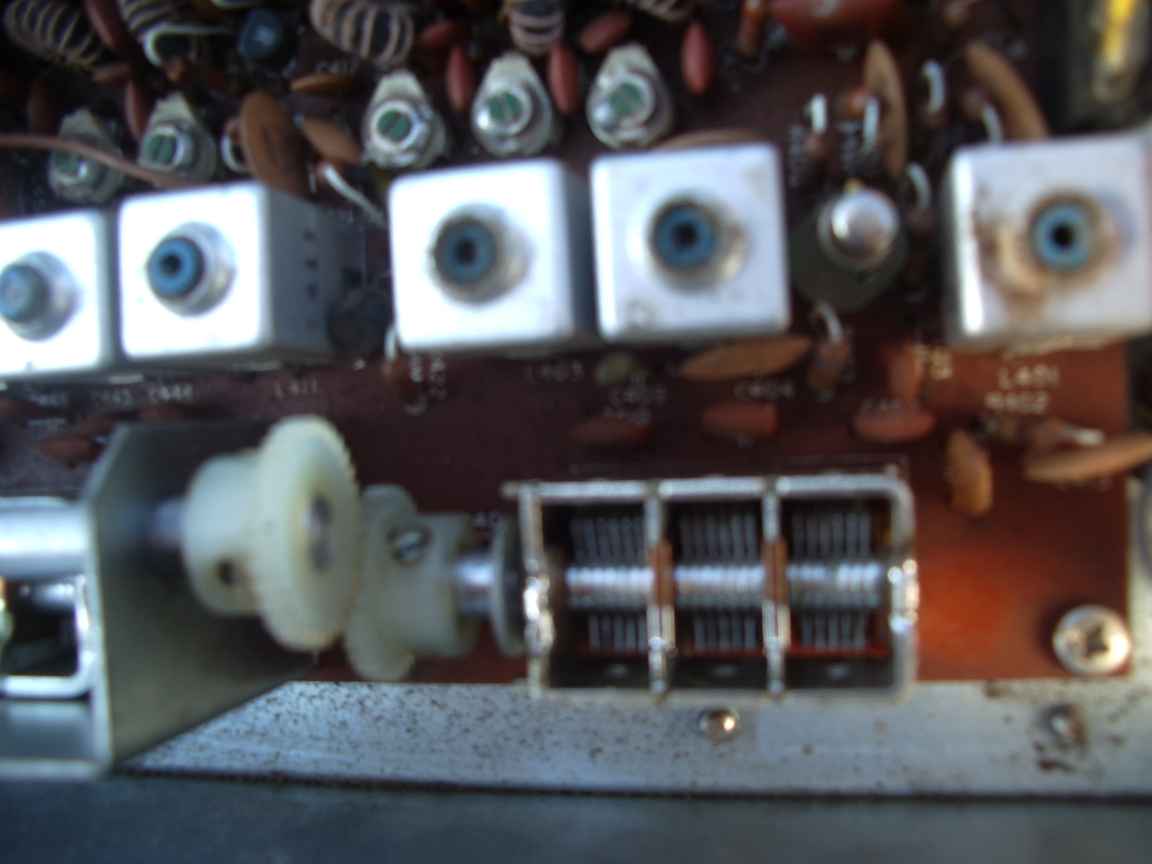
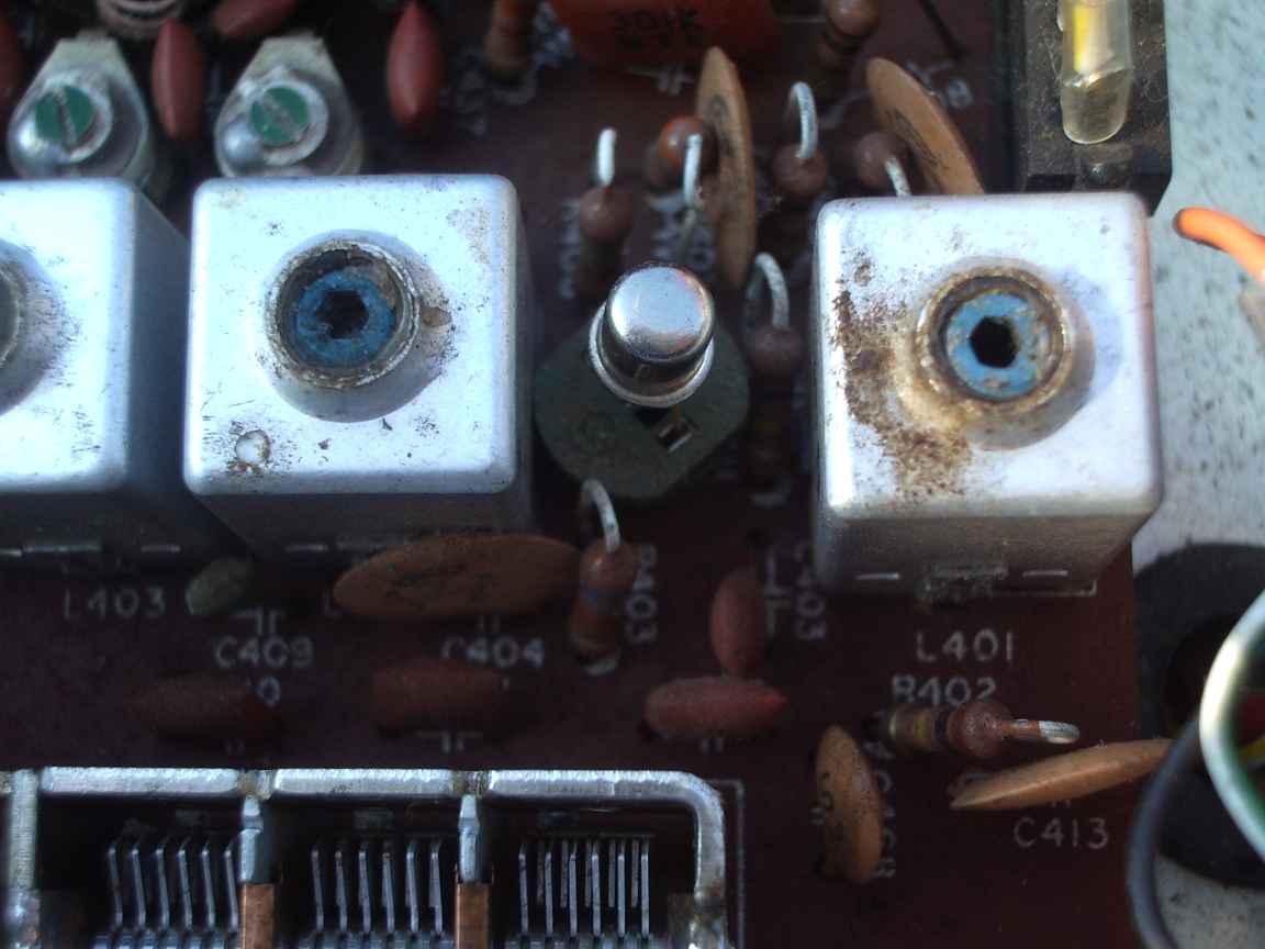
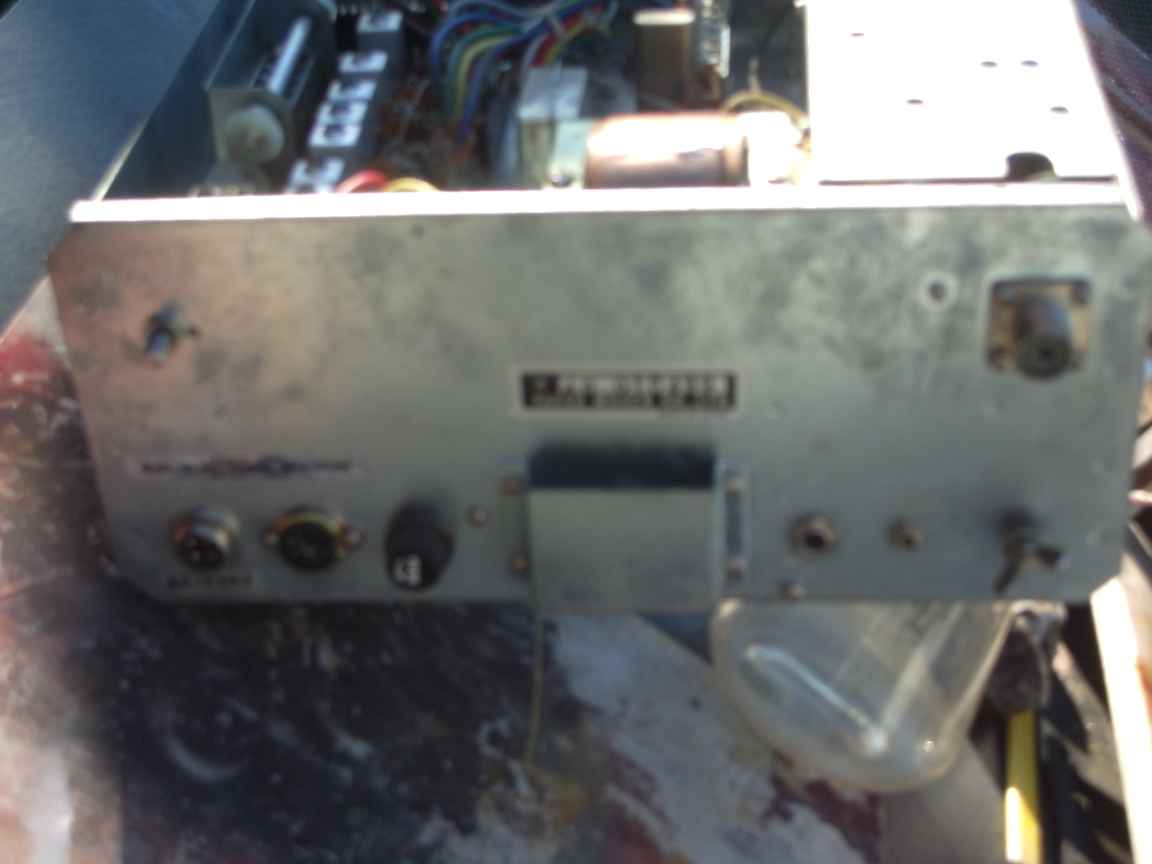
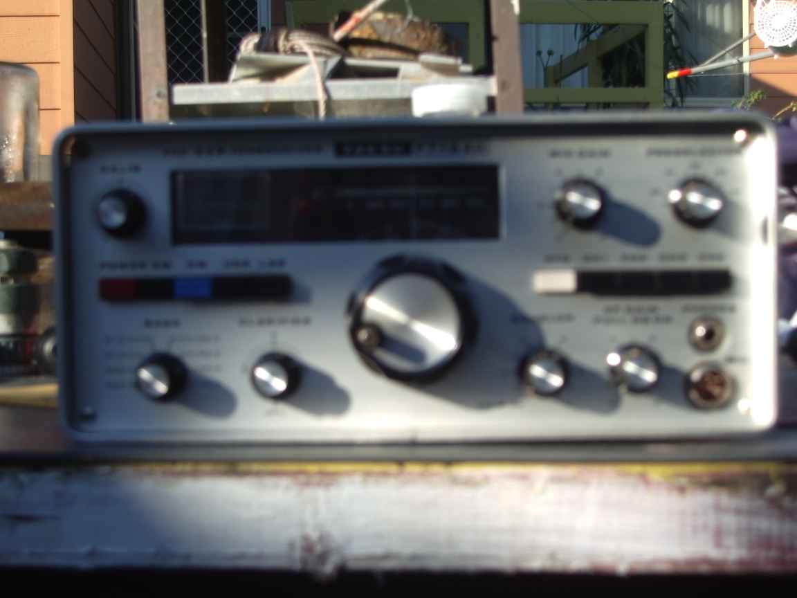
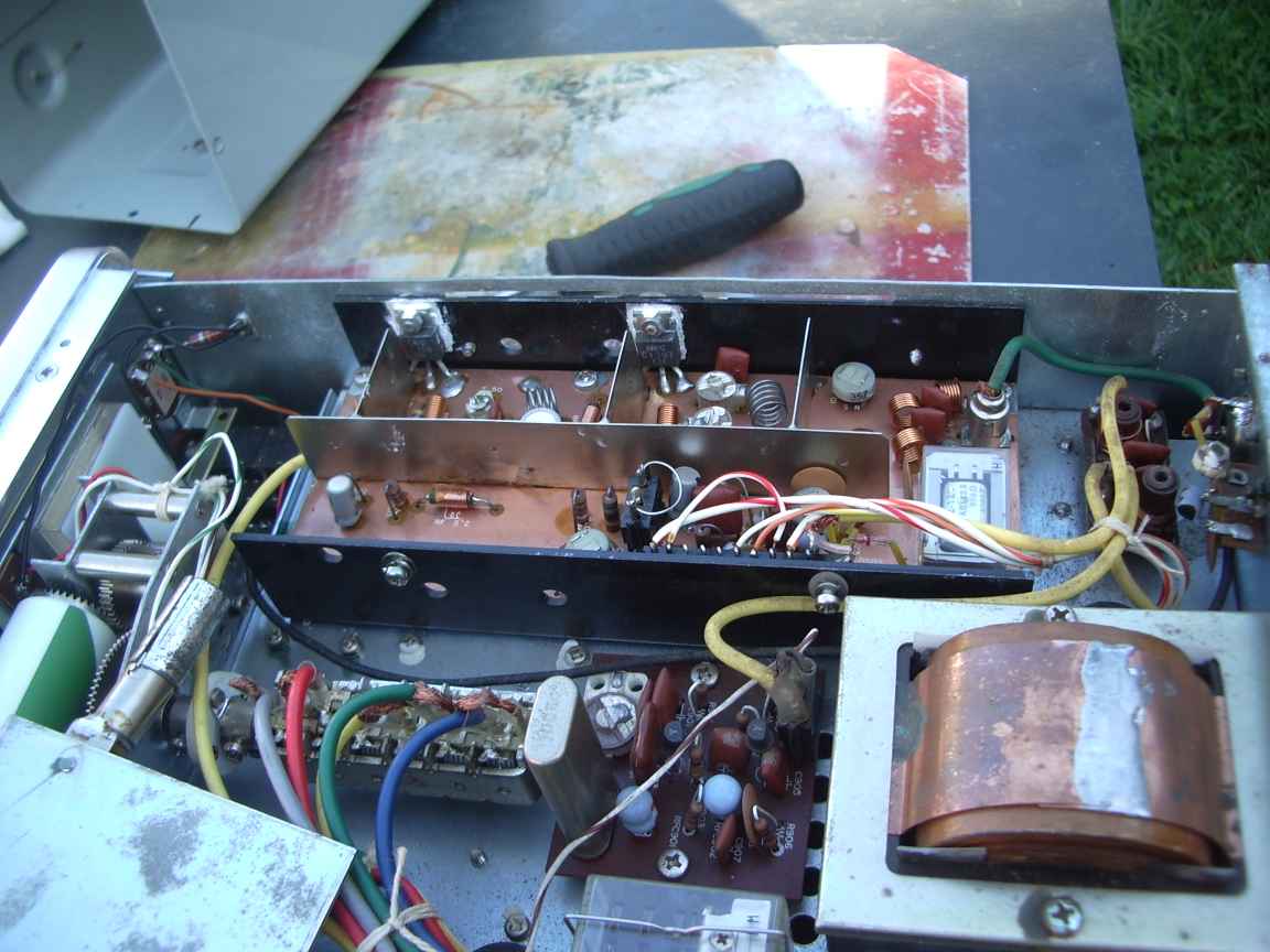
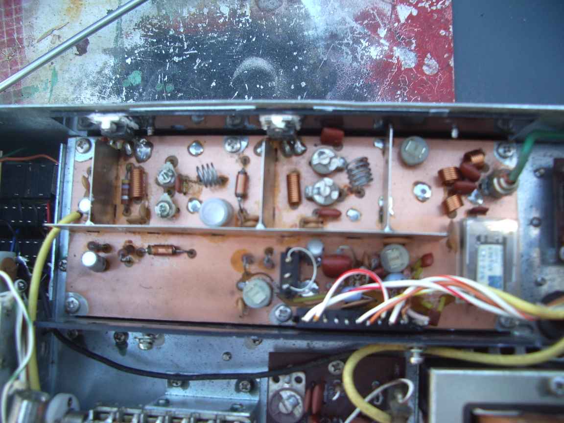
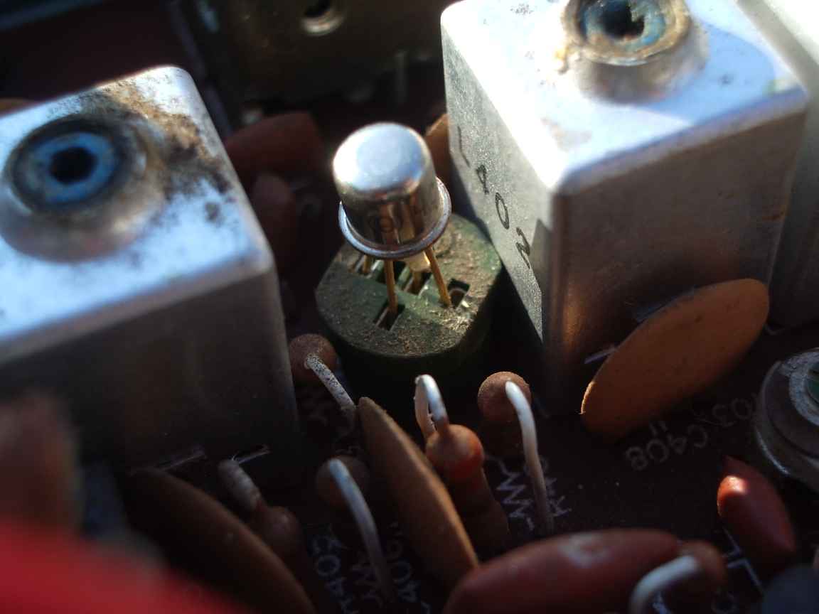
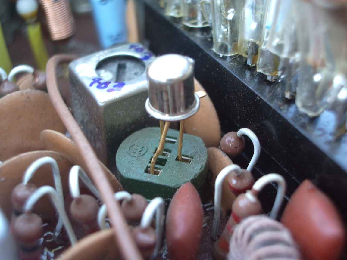
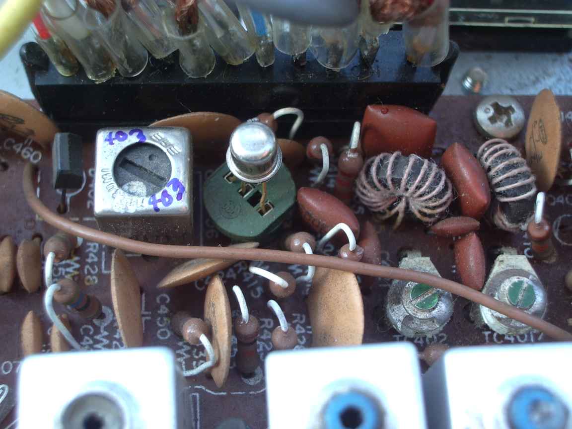
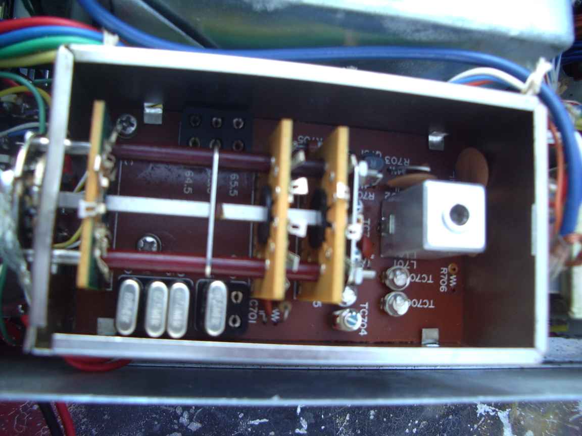
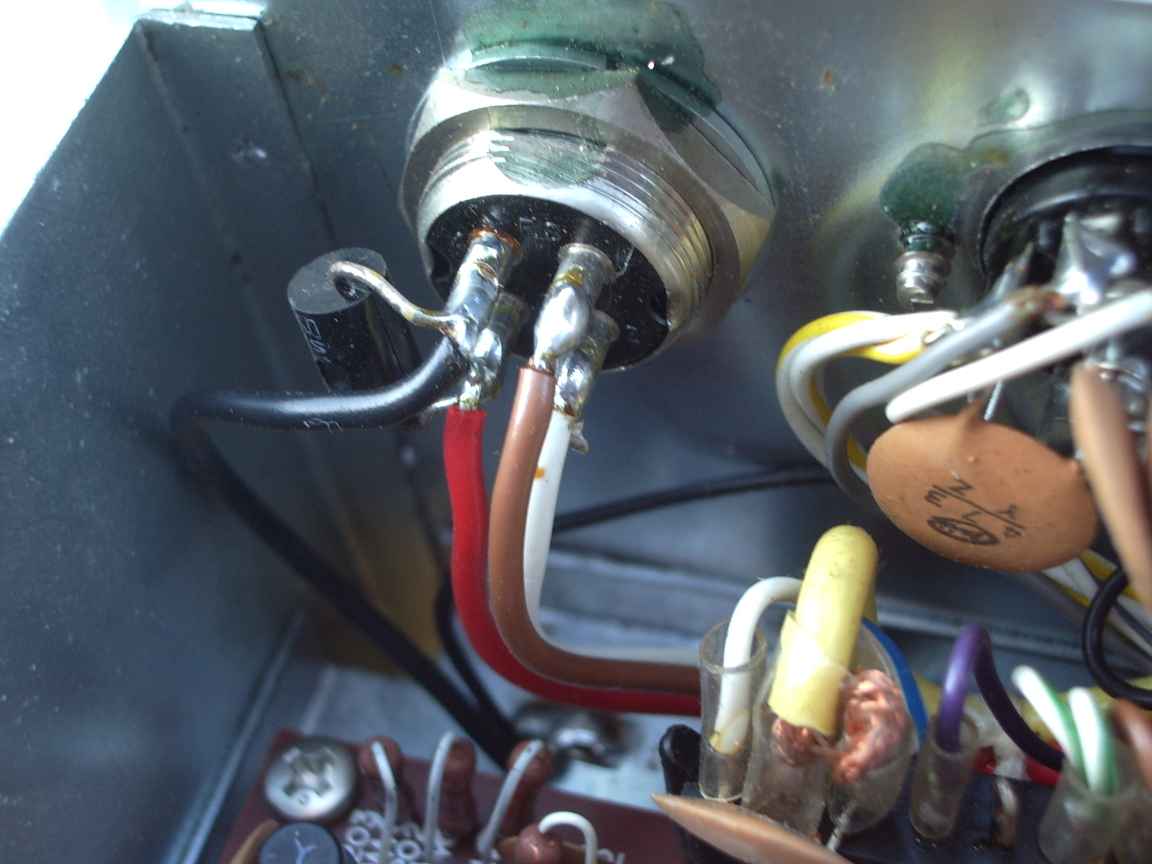
Despite the physical condition being excellent, and would you believe in its orginal box, this unit needs significant work to render it usefull. The radio dates from the early nineteen seventies, and as such, is devoid of digital logic and its attending phase lock loops. All internal frequency references are created from a collection of 20 or so quartz crystals and a very nicely constructed 5-5.5 Mhz vfo. It was designed to be completely tuneable from 50 to 54 Mhz. The designers of this radio must have been working with vacuum tubes for most of their professional life because this design is a valve design, but implemented with three-legged fuses ! For a narrow range radio there is a lot of bandswitching going on and a lot of clockwork ! The vfo is beautifully controlled with well made clockwork reduction drive. Disturbingly, there is plastic clockwork in a major part of the circuit, the 1st and 2nd transmit and recieve IF stages. There are 10 gang tuning capacitors to tune bandpass filters over the radios operational range . These days one would not bother. 50-54Mhz is hardly "wideband". These days all this would be done in wide band stages, devoid of operational tuning controls. But this is a "valve" design, many critical stages done with first generation mosfets and jfets to get all the benefits and limitations attached to "high impedance rf design". But this was how you did things in the late sixties, only the millitary had access to alien technology like broadband design.
What is wrong with my unit ? Not much, actually. So just what is my beef ?
I was dissapointed to discover that my new FT620 was more deaf then my ancient valve based millitary C42 set !
Then, shock horror, despite the radio claiming to operate 50 to 54 it only worked from 52-54. There is a perfectly reasonable explanation for this. Untill 2014, Oz radio amatuers only had an 52-54 allocation and latterly, a severely limited "sliver band" at 50-50.2 Mhz because we were cursed with TV channel 0. We must all bow to the mighty idiot box. These days Oz amatuers have the entire band back. It only took 35 years of lobbying the Minister. But we got there in the end !
The crystals to cover 50-52 Mhz in australia would have been a useless and very expensive option as no less than four are so required.
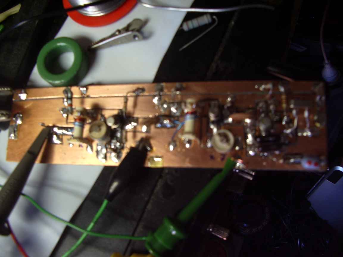
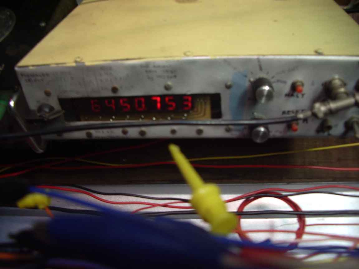
So, where to from here? I need to retune the front end and first IF and replace the somewhat maligned front end mosfett with a "hot one" like a 3N201 which by good fortune my junkbox contained. Our SSB segment where what pathetically little activity takes place here in Oz is only 50.1-50.250 so I only really need one little sub-band to work. I do not want to spend over one hundred dollars getting a a custom crystal cut for 64.5Mhz. Was there something in my junk box that was even remotely right ? There was a 9.125Mhz crystal that when 'heptupled' came out about right. Now then, doublers and triplers are easy. Your mileage may vary with quadruplers but still work well with a hot transistor. Quintuplers just get hard,
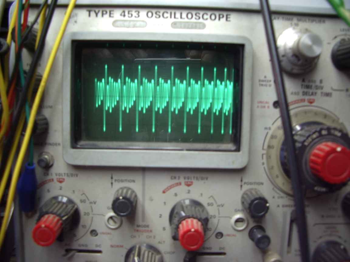
hextuplers are horrible and heptuplers and just plain crazy. So it looks like its going to be a heptupler ! Would my crystall oscillate in 7th overtone mode ? Maybe, but that is just as farfetched as a heptupler. could I mix a 40Mhz OScillator with a 24.5Mhz crystal i just happend to have ? If the heptupler turns out to be useless this is what will happen. News and Pictures at Eleven ! See below, the heptupler despite what everything we learned at Radio School actually works...mostly.
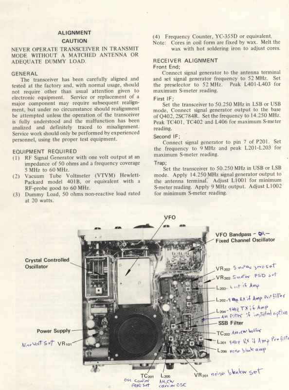
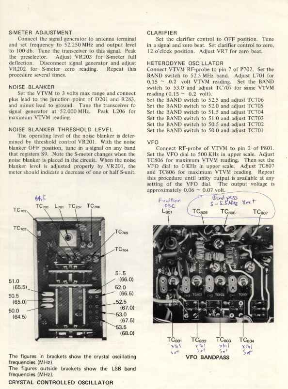
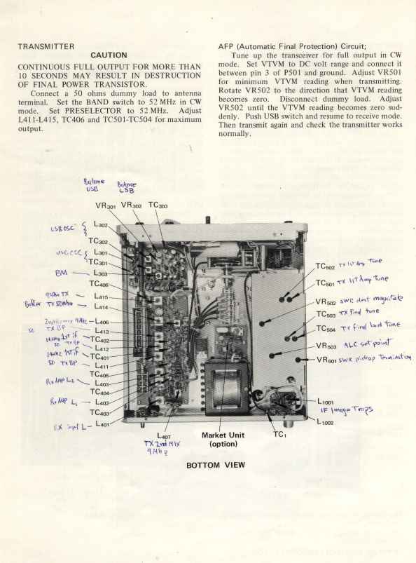
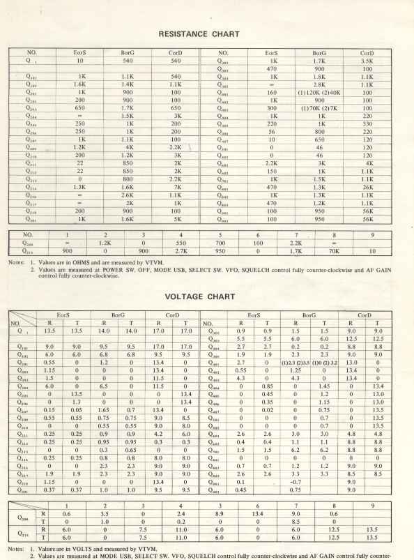
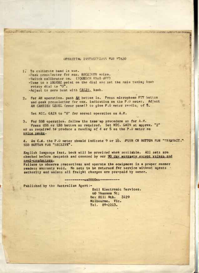
The unit came with the instruction manual !, that ommits the tuneup procedure. It advises that only the factory can carefully tune it. So I am on my own.... I will write up a tune procedure, the "multiband" nature of this radio will make it troublesome.
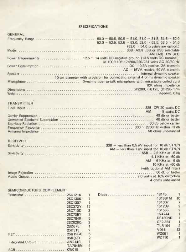
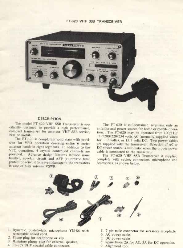
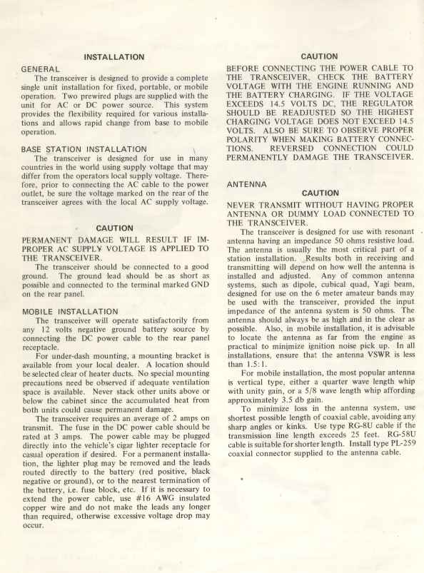
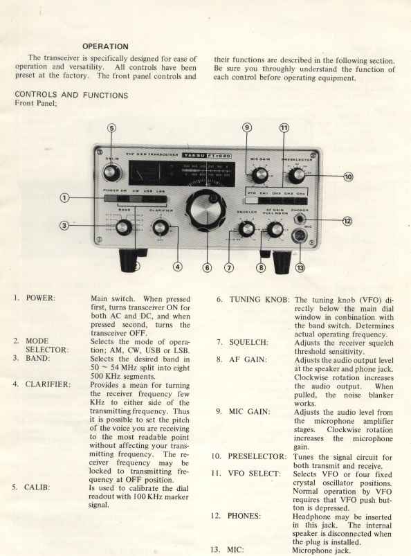
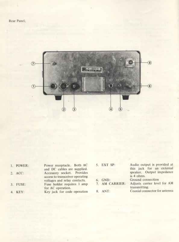
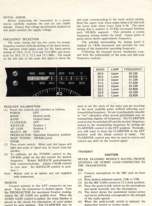
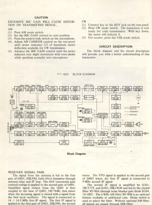
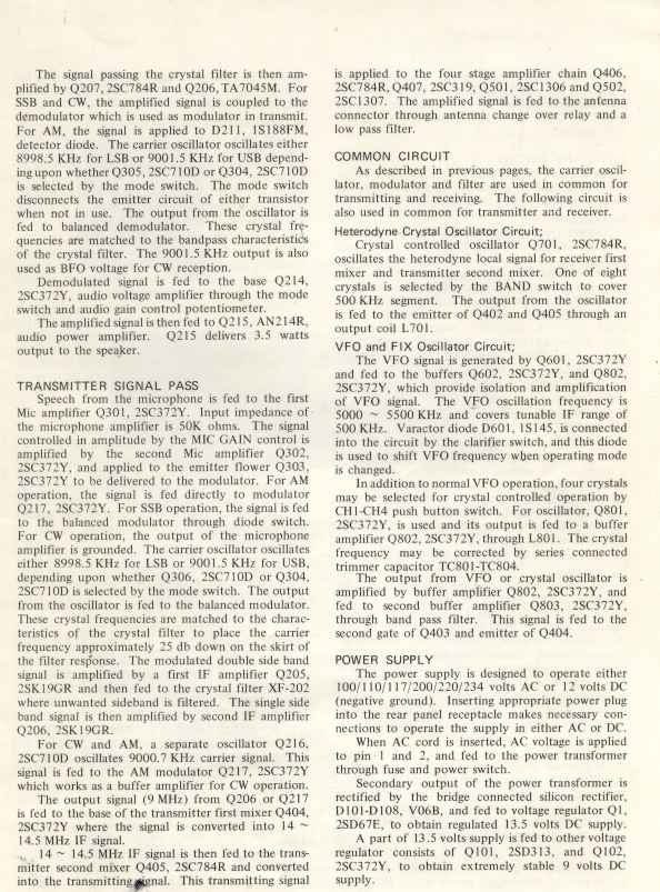
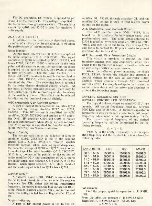
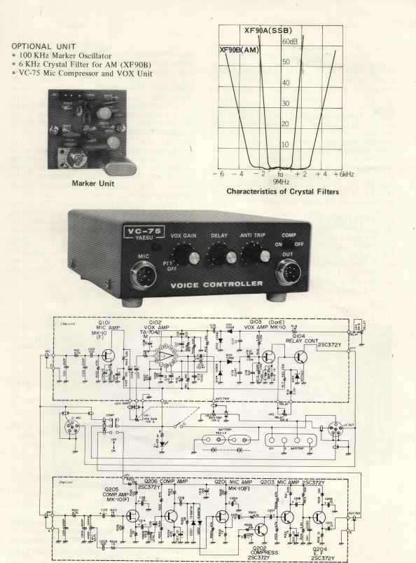
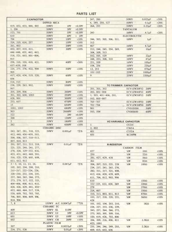
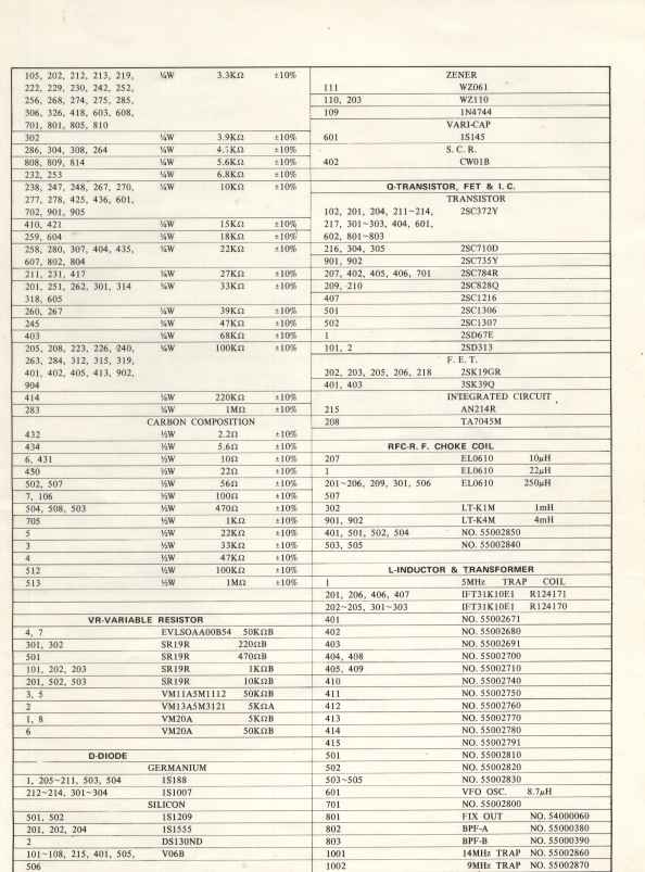
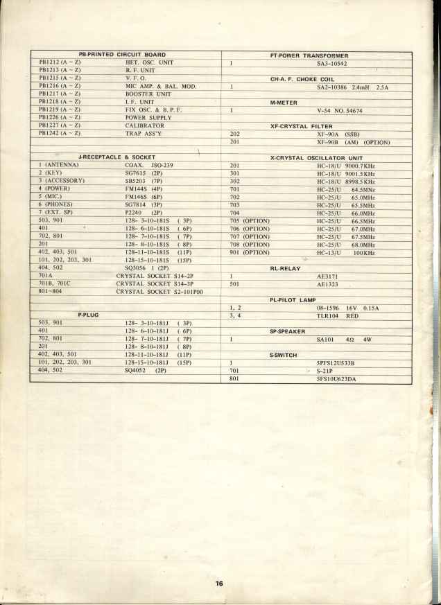
I present here a high quality scan of the manual and schematics in the hope that other hams that may stumble on this good little radio at a hamfest can make use of it and learn about a forgotten phase of radio design... and bring some life to our empty 6 meter bands. I hope you find my annotations on the circuits helpfull.
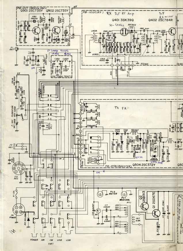 | 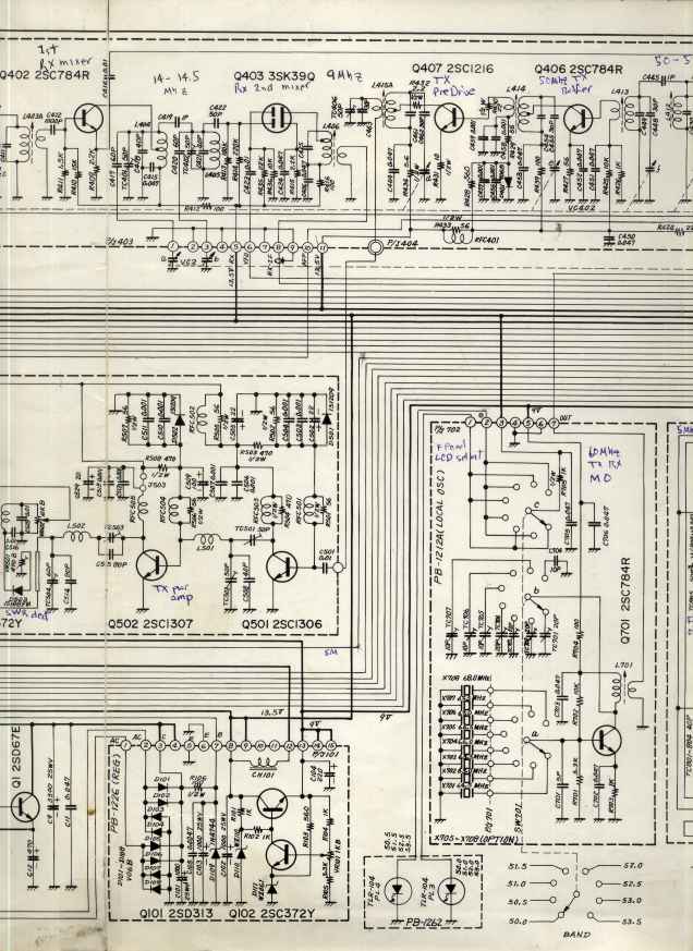 | 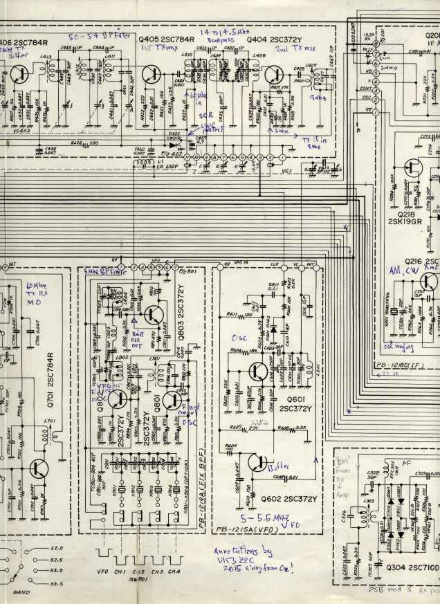 |
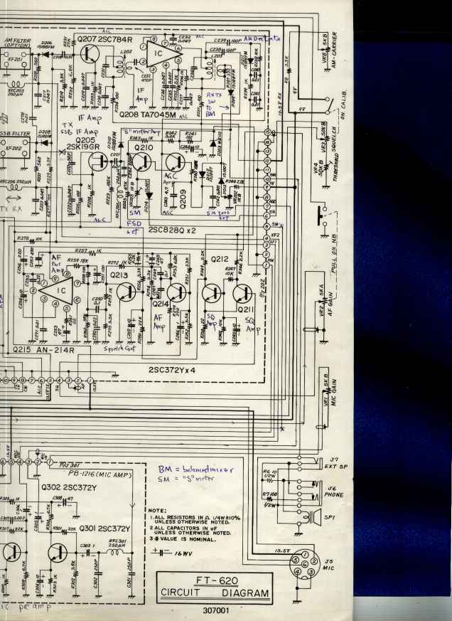 | 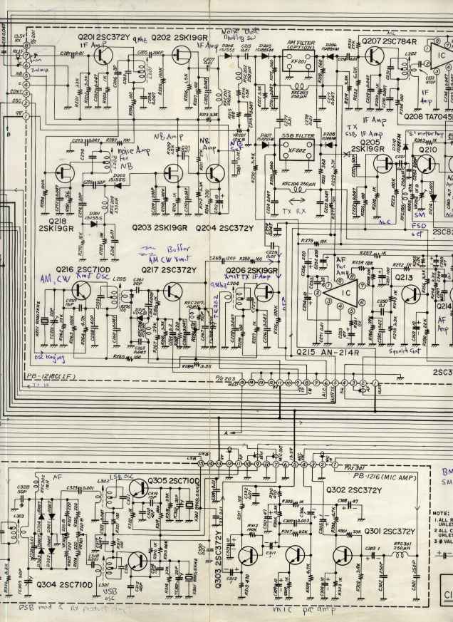 |  |
| these are un-retouched full resolution scans. clicky and print out full resolution and cut and paste them yourself. Hope my annotations proove to be helpfull. | ||
 |  |  |
 |  |  |
 |  |  |
 |  |  |
 |  |  |
 |  |  |
further news as it comes to hand
homepage
