So after a long sleep of 70 years , would this antique work again ?
Yes !
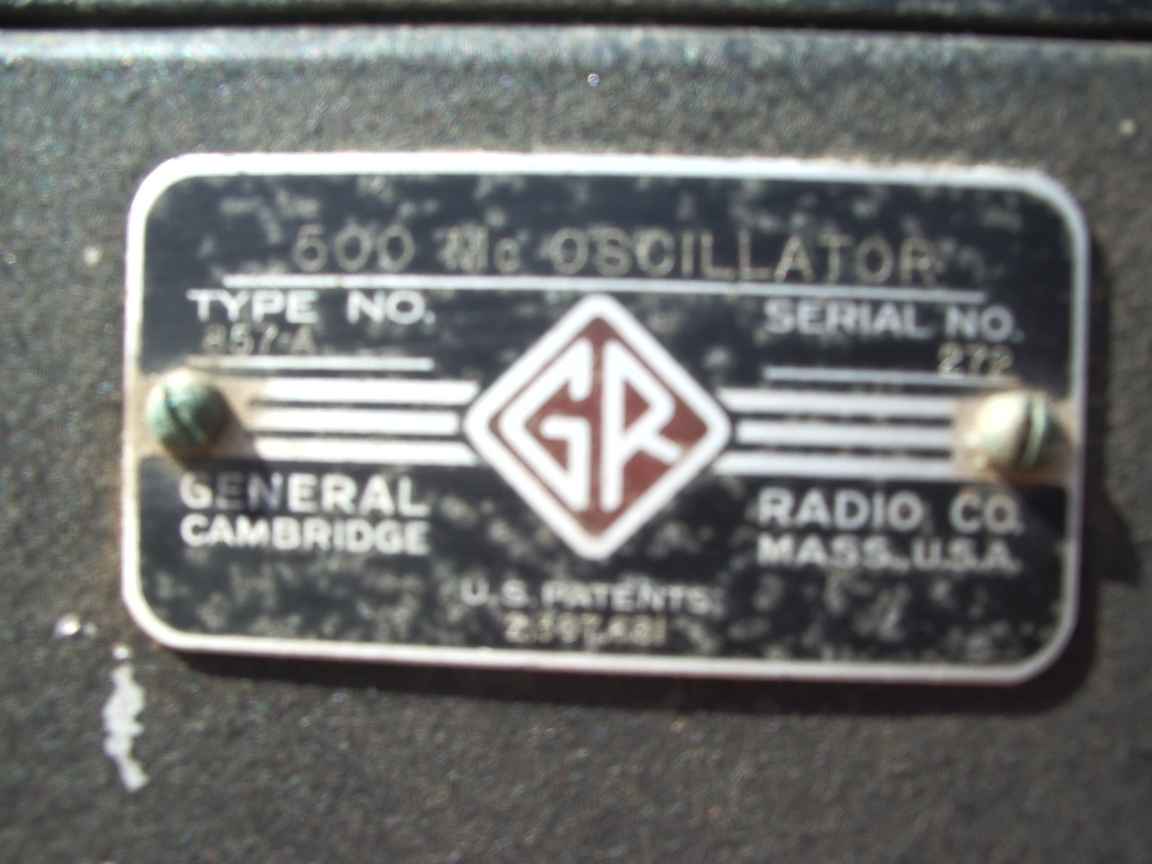
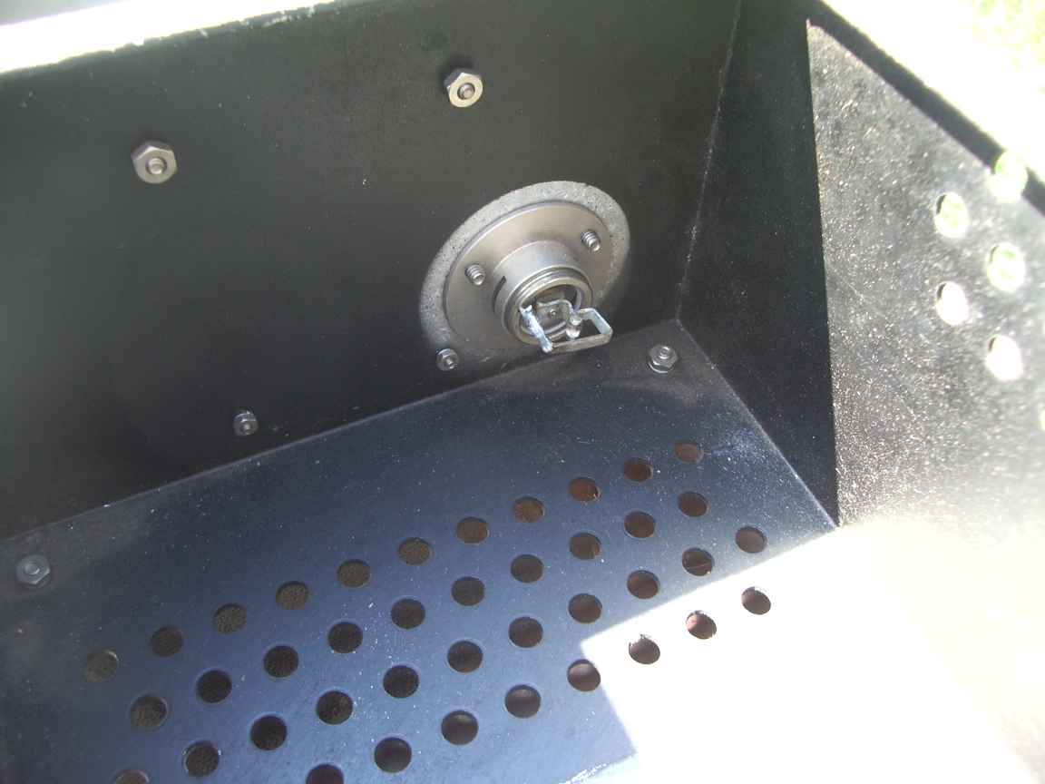
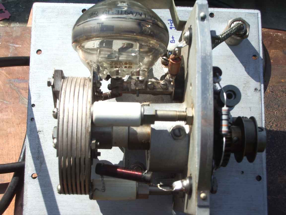
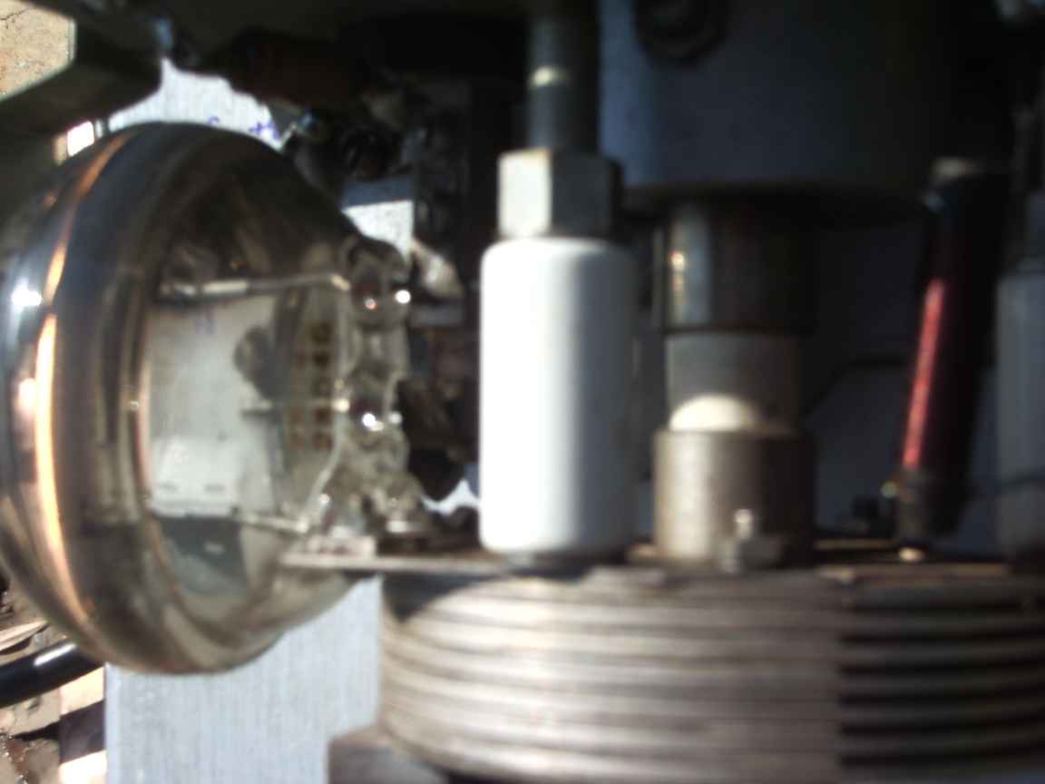
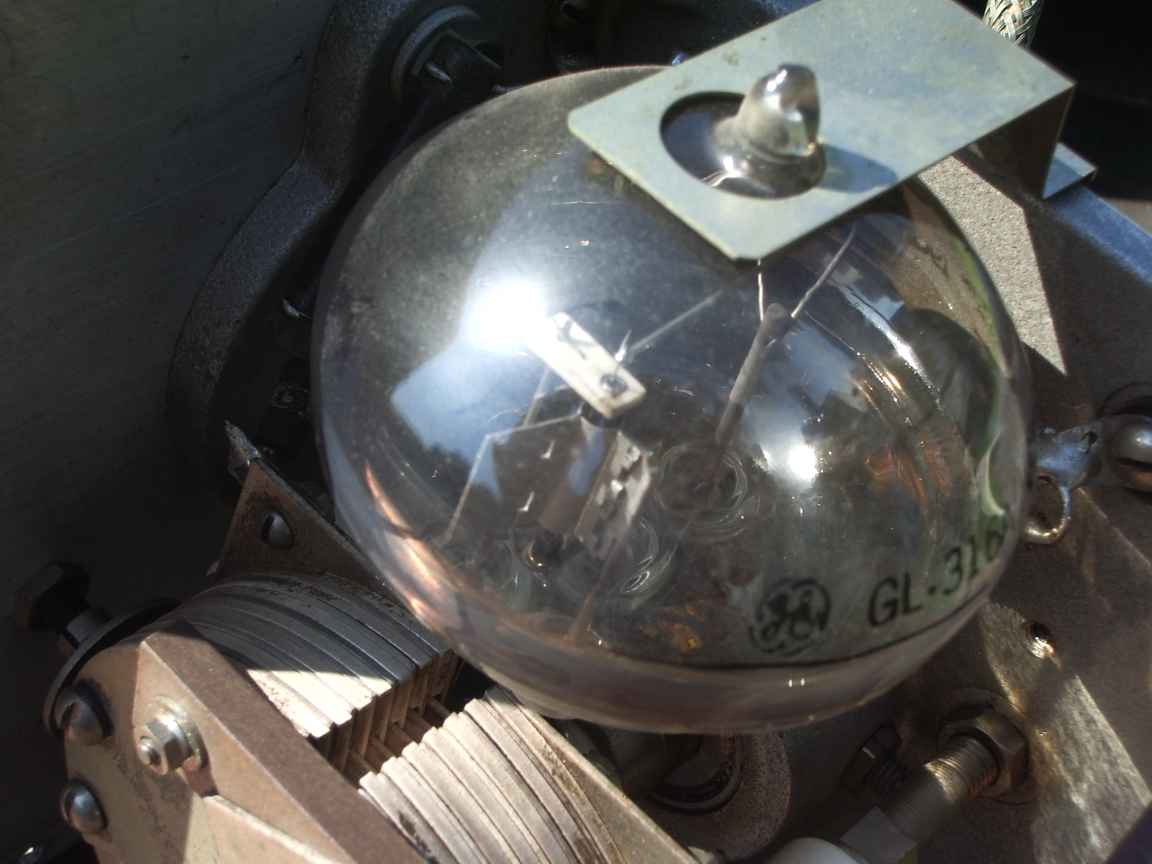
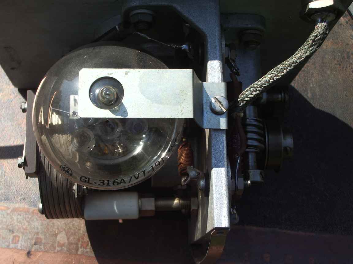
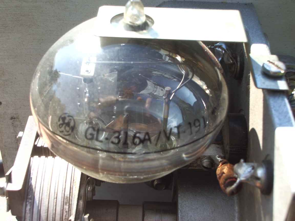
It was possible to download the GR catalogues and a service note from IET laboratories that maintain the GenRad heritage. The filament of this antique triode is a thoriated tungsten directly heated cathode that wants 2.2 volts at 3.5 Amperes, an odd voltage requirement to be sure. I had to hand wind 30 turns through a surplus toroidal mains transformer ( a great way to light up old Transmitter Bottles with odd filament voltage ). The original unit was meant to be operated with the GenRad custom power supply which included a grid leak resistor and metering of grid current with a magic eye tube, this being used due to war shortages rather than a more usefull moving coil meter. This could make the instrument behave like a grid dip meter.
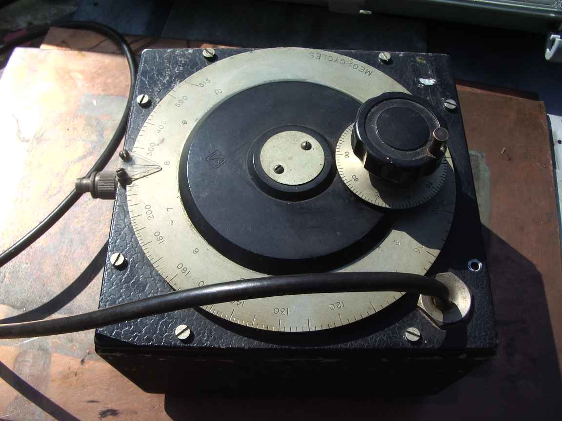
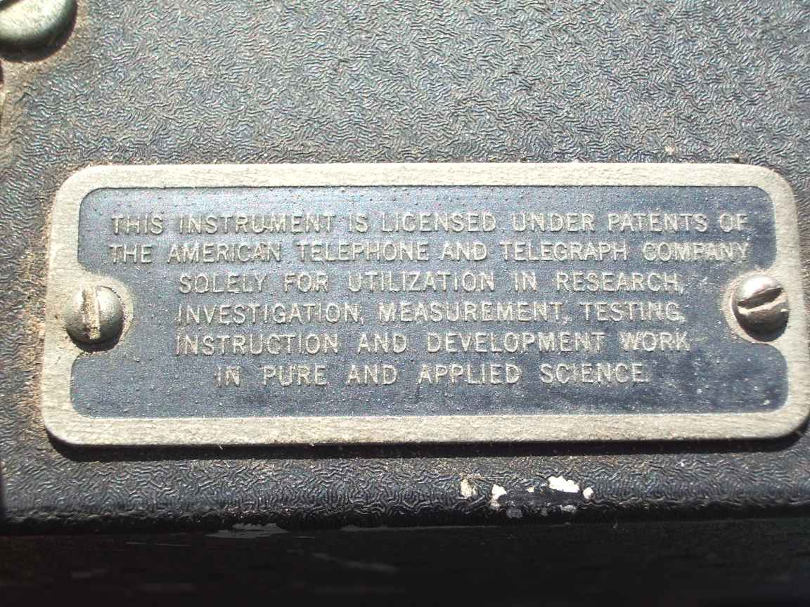
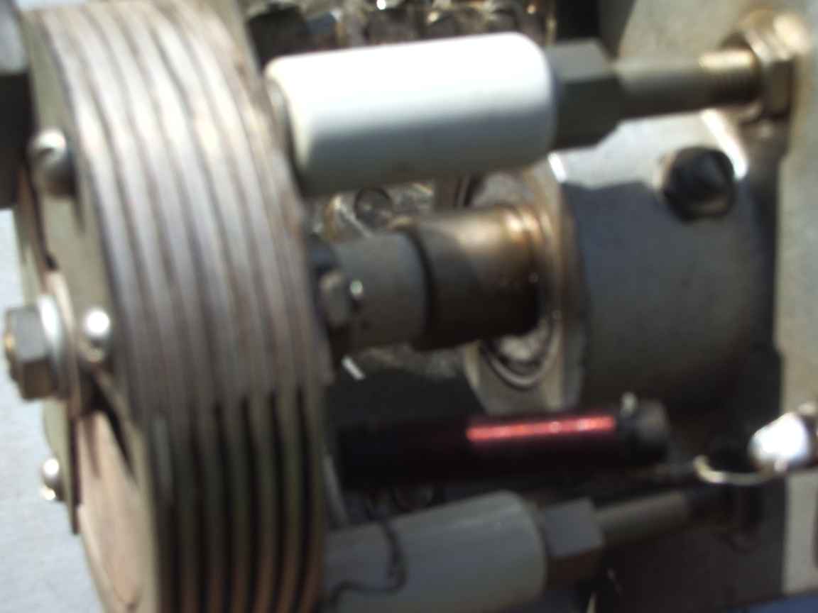
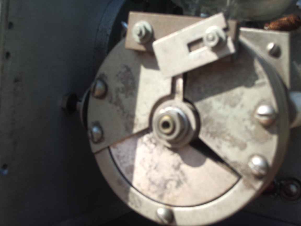
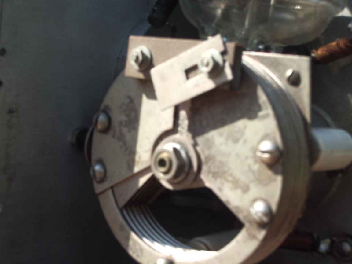
It tunes from 90 Mhz up to the dizzying heights of 515 Mhz which was considered microwaves in those days. The anode on the triode is made from molybdenum and can dissipate about 5 watts of power. The oscillator was rated to produce up to 1 watt of output power. At this power level the anode will glow dark red. The real gem in this unit was the resonator that permits 2 octaves of tuning range without band switching ! Thats why the resonator design was patented ! Just try tuning
100-500 Mhz with a variable capacitor or varactor...it cannot be done.
The oscillator despite its single triode has remarkable frequency stability due to its solid cast metal construction and the extremely high Q of the butterfly resonator. After 1/2 hour of warmup this can be netted on a narrow UHF chanel and it just stays there. Absolutely amazing ! Even better with a stabilized power supply. Frequency stability is still a function of output coupling as you would expect.
Powering up for the first time in 70 years.
The filament is meant to run at bright yellow heat and emits a lovely bright warm glow in operation. Original cost in 1944 was $250 US dollars, a small fortune at that time. I let the filament condition itself. Really antique thoriated filaments should be run at their rated current for a few hours without applying high tension. This gives time for the thorium to migrate to the filament surface and permit outgassing. It is the thorium atom layer that supplies the electrons, not the tungsten, which is an electron emitter only at white heat. The initial current draw at 250Volts was 70mA which is way too high. This stabilized by itself in about 30 minutes. I expect that this was due to filament outgassing and the tramp gas before making its way to the getter. Do not permit anode hight tension to remain if the oscillator stops. Otherwise ,Substantial and destructive anode current will flow because grid leak bias will not appear to limit anode current. The anode is Molybdenum and will tolerate a some abuse.
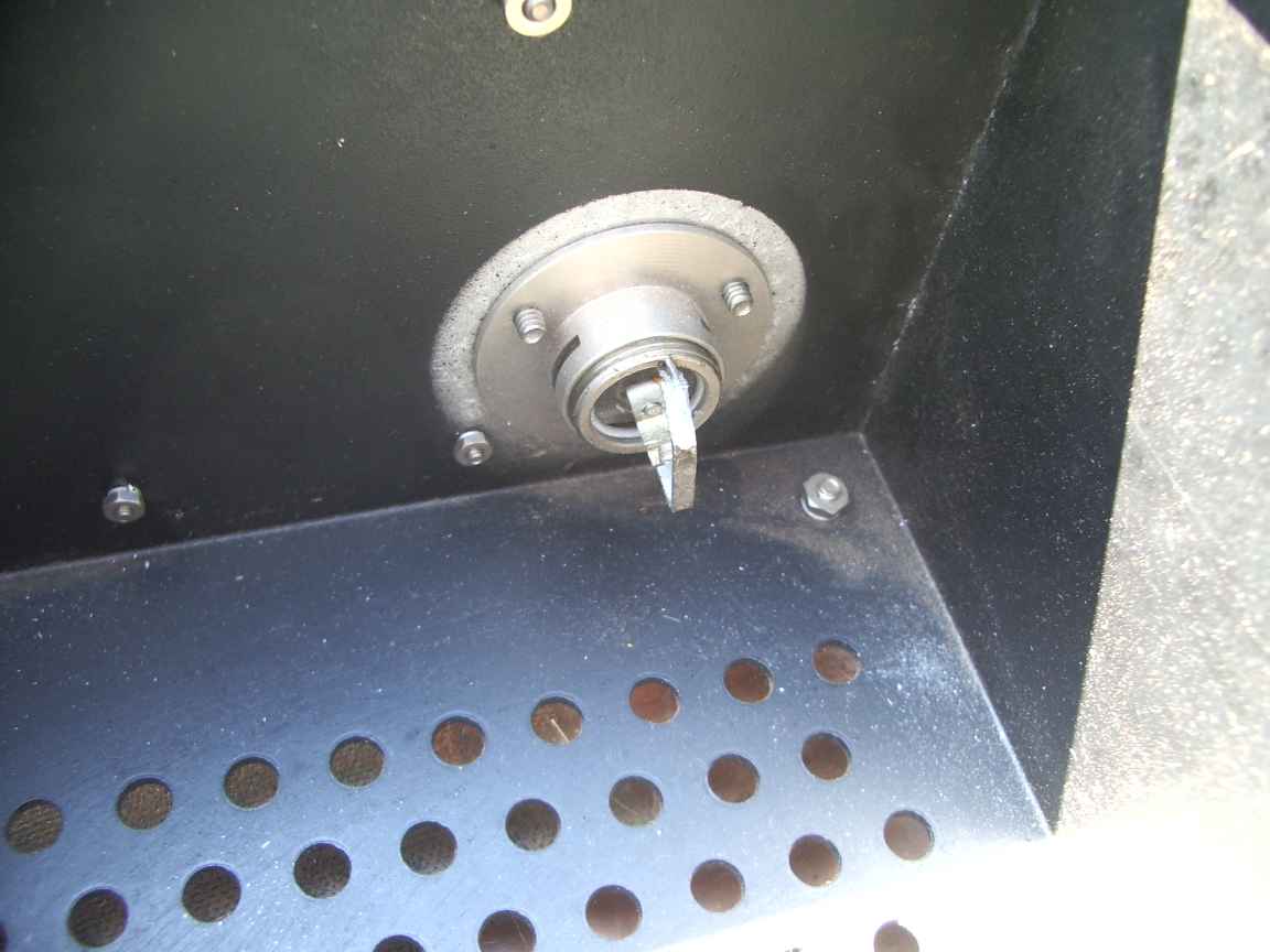
The output coupling link can be rotated to vary the output power. It should not be rotated all the way in, this will result is too much power being removed from the resonator quenching the oscillation, particularly at the upper frequency limit of the unit.
Frequency stability after a long warm up period is superb.
The General Radio instructions specify 350V for the anode high tension, mine works fine at 250V.
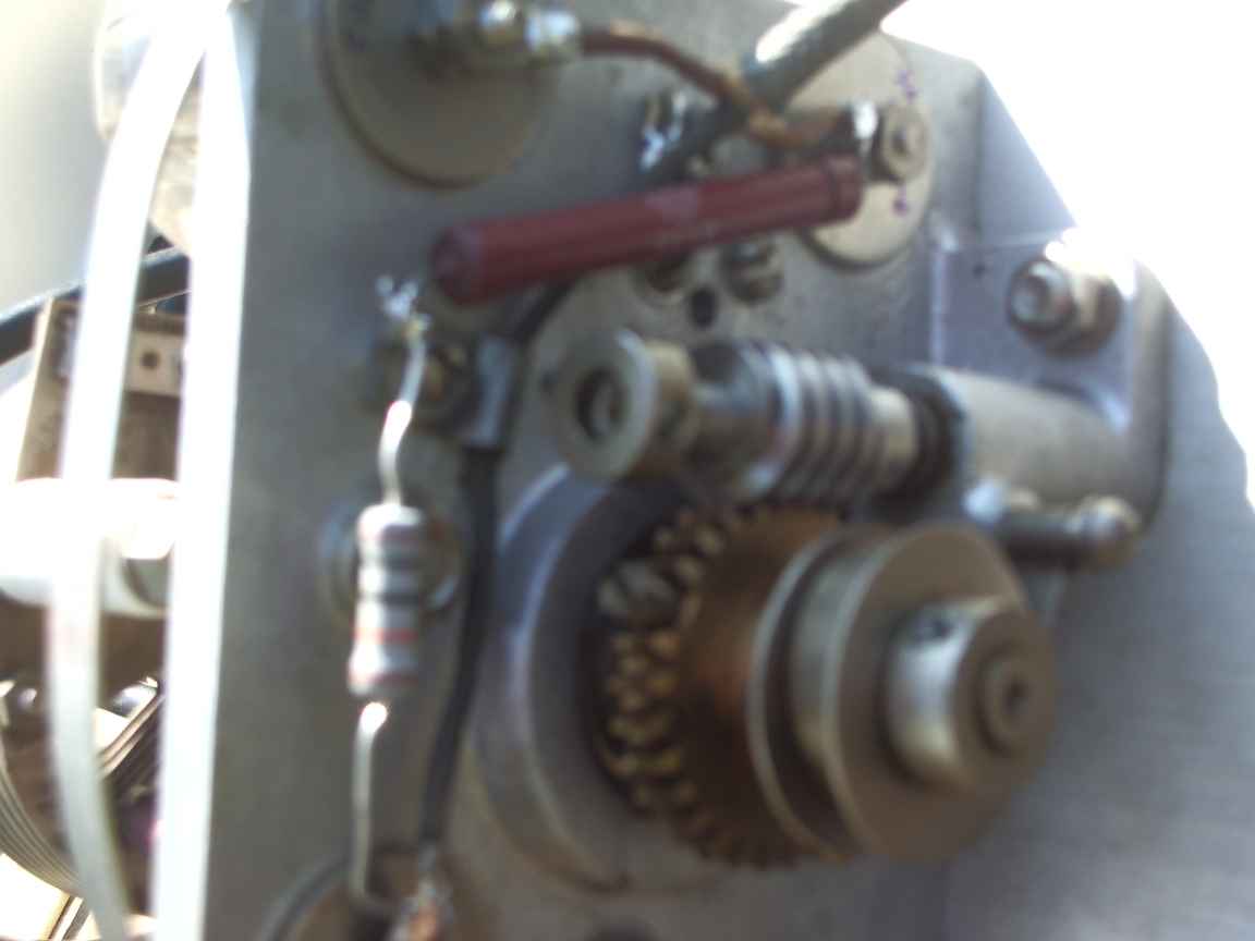
I used carburetter cleaner to dissolve and remove the ancient, completely dried out grease on the gearing and put a little dab of modern teflon grease on the worm. The sealed ball bearings were still serviceable.
This oscillator would have been used for deci-metric radar development, it would have been too expensive for day to day field alignment work. I wonder what it was doing in Australia ? It will find a second life in the shack for tuning my UHF and VHF antennas.

 2-april-2014 first draft