"use a transistor, go to gaol, its the law !"
Forty years ago I salvaged all these 6CM5/EL36 tubes from discarded TV sets thinking that one day I would find a use for them. That day has come. This project will attempt some difficult things and pioneer an old but neglected inductor design. I like to push the boundaries so I shall attempt to harness 8 TV line output tubes in parralel and re-introduce the conical inductor for both anode tank and anode RF choke.
At the recent Werribee hamfest, I bough an armfull of old 6CM5 bottles for only $2 each ! How to choose them ? Look at the getter. If its bright metallic and lustrous then this is a must buy bottle. If it it has become brown the tube has seen much use and the getter is loaded with tramp gas. It may still be useable , test before use. If the getter is white, this marks the true end of life for the bottle; it means the tube is open to the atmosphere.
I am well aware of the traps of putting valves in parallel and the resulting strange untameable VHF oscillator that can result. I hope to work around this with heavy grid loading, low Q screen grid bypassses, heavy Kathode degeneration and generous use of lossy ferrites and the benefits of low output impedance that the parrallel design offers. The use of the conical inductors that will exhibit fewer parasitic resonances will also reinforce the tendancy towards stability.
The 20 Watt plate dissipation of the EL36/6CM5 of 8 of these old bottles should allow me at least 200W CW and just under 400W PEP for ICAS speech if given plenty of forced airflow. The power supply can be nicely obtained with a new very old but still serviceable TV transformer which I have hoarded for 40 years.
This is a "high power" project by Australian standards, the authorities do not allow us to even aspire to "kilowatt input".
I used these bottles because they have cost me nothing, cost $2 at hamfests and just work. I am not comfortable about using high power solid state transistors simply because your first mistake is your last, and, they are costly.
This design and and more forgiving nature of thermionic valves permit opeartion into a wider variety of load impedances than an equivalent solid state design. It is very hard to find an antenna that is "50 ohms"
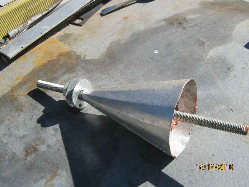
The conical inductor for HF choke attempts to bypass a problem with cylinderical coils and their strange resonances. At some frequncy, the winding length becomes like an equivalent 1/2 wave line, which turns the choke into a short circuit and the central part into a tesla coil , whoose corona will rapidly erode the choke. The stepped pie wound chokes found on classical transmitters are an approximation of the cone inductor. Conical chokes are making a comeback, a firm called CoilCraft is making them for microwave bias lines specifically for their broadband performance. The cone has less common magnetic flux lines linking the turns, this creates a model of many "perfect" individual inductors in series. The cones were discovered in the 1920's but proved unpopular due to the mathematical difficulty in predicting their inductance; and they required for special mandrels for winding them. My RFC cone has 137uH as measured on my GenRad bridge, which is a usefully large inductance for choke applications. The choke will be placed at the "cold end" of the PI output coil. This will eliminate much of the troubles associated with broadband RF chokes. This means that the tap selector switch and the coil and tuning capacitor will be at EHV potential. This is a break with the standard transmitter design orthodoxy and also makes this design hazardous. Be warned if you try to copy this idea.
The purpose of trying a conical inductor in the anode tank is to improve the Q of the inductor. By tradition, the anode PI tank is tapped and switched. The unwanted part of the coil is shorted out. Magnetic flux from the "active" part of the coil is still threading the shorted turns causing a circulating current. This current is subject to ohmic losses and serves only to reduce the amount of energy in the tank circuit, that same energy that you have commited so much time effort and money to produce ! By shorting out the tip of the cone, far less magnetic flux is coupled to the shorted out section. This has the overall effect of increasing the overall Q of the inductance. There is also the benefit of less chance of exiting a stray resonance. Measurements of Q and Inductance on my bridge seems to confirm the soundness of this idea. I should also add that winding the cone was extremely difficult with the heavy gauge wire . The secret is to wind the small end first and not to stop untill the entire winding is completed. The spiral will unwide itself somewhat, never mind, the unwinding is small but does increase the diamter of the cone. Take this into account if the available space is small.


to be continued
Tue Mar 14 18:40:25 EST 2017 added progress images. It is not working yet. So close but yet so far !
....they may laugh, but Ill show them....bwah ha ha ha ha