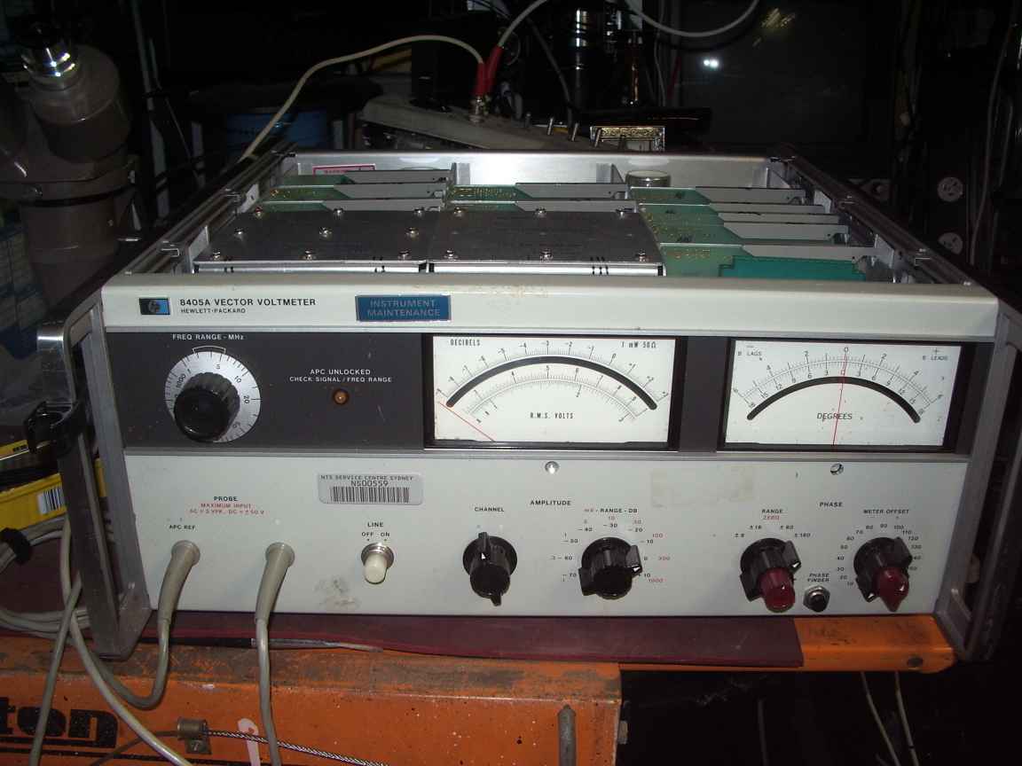
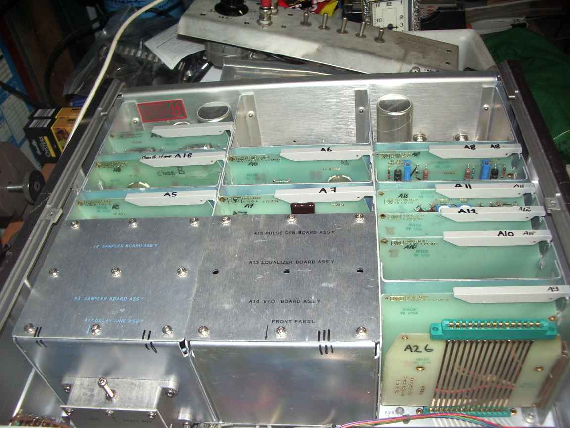
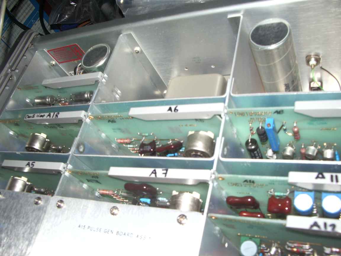
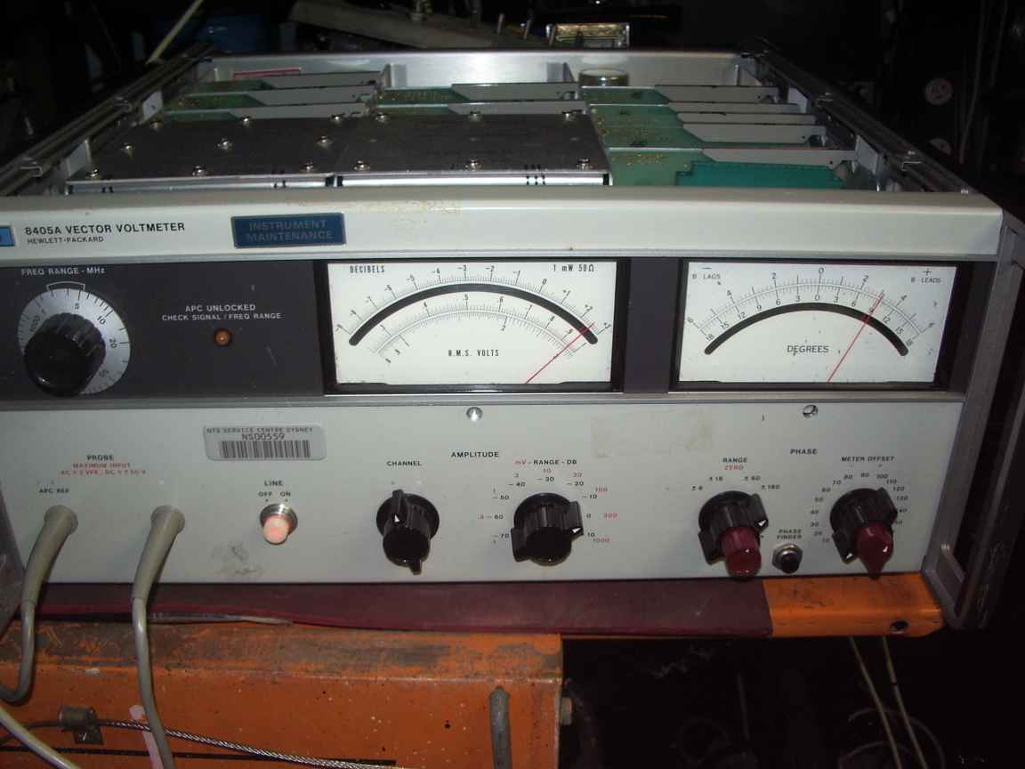
The electronic design is amazing is the way that the signal being measured flitters between the time and frequency domains. The instrument measures both amplitude and phase by down sampling (or mixing ) to 20KHZ (where it is easy to amplify and process) a specially crafted pulse train that varies from 1Mhz to 2Mhz whose source is a voltage controlled oscillator. The pulse train is very rich in sidebands and soon, one of these mixing (down sampling) sidebands will be in the passband of the 20Khz IF chain and phase detectors.
One of these detectors serves to phase lock the voltage controlled oscillator to a sub-divisor of the input signal. Once locked, the 20kHz signal in the IF amplifyer is a faithfull replica of the input signal. The phase of the down sampled signal is also a faithfull replica of the input signal from the B channel. It still surprises me that this is the case, even though I should have known this from my University Maths.
(my feeble excuse was that my Math is 35 years in the past) . The downsampled phase pulses are integrated in a simple low pass filter to directly drive the phase meter. This design is brilliant ! How else could you measure phase at 1Ghz in 1966 ? with the active devices in existence in those days. I still remember how silicon transistors were regarded as "exotic" in those days, when a germanium device with a 2Mhz fT was regarded as an "RF" device !
This device requires some practice to use effectively.
The A chanel must be used to create the absolute phase reference. Only the A chanel can be used for doing standalone level measurements.
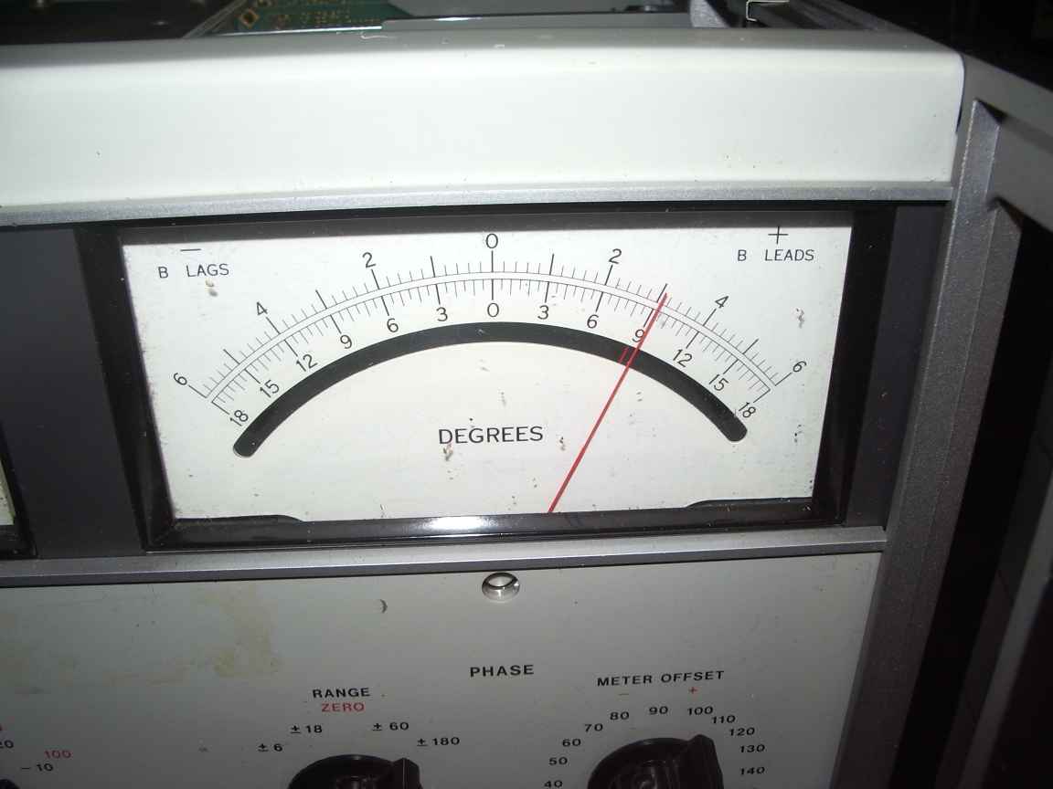
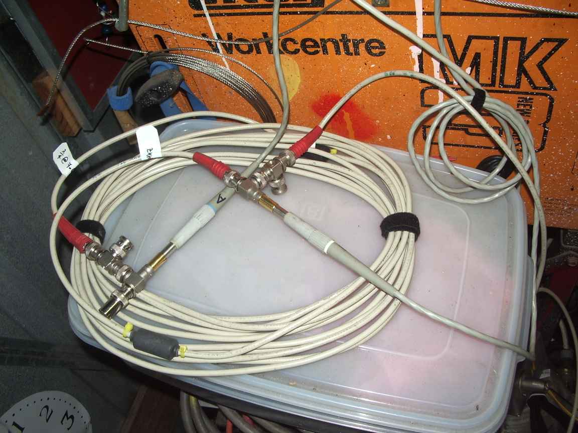
The little lock light must be OUT before any measument is meaningfull. Only once we have a stable A CHANEL reading can you probe with the B chanel. Otherwise the phase meter displays jerky random looking movements. You might think ( as I did) that the B chanel is faulty. This is not the case. You cannot use the B chanel as an RF millivolt meter standalone. A valid A chanel signal must be present first. Ind the first instance, short circuit the A and B chanel probes on a valid RF source. This establishes the ZERO phase reading, adjust the phase controls to achieve this. Now insert the B probe on the circuit to be measured. The phase meter will read the B probe's phase with respect to the A Chanel. It may lag or lead as the laws of physics and mathematics decree. When the instrument is locked to a valid A chanel then and only then can you select the level on the B chanel. Now you have both an A chanel reading with 0 degrees phase and a B chanel amplitude and phase differance. You have just measured a Vector !
Coming up. There are two manuals currently on the web.. One from the BAMA which is quite good and another from a MIL site which has notes added by the military to help GIs repair this instruments in the field ... in places where HP did not do field repairs ! I am touching up these schematic images with the GIMP to make them more printable and readable. I will release these soon. I will also write an essay about how this instrument works, when I understand it better myself !
unretouched manuals
8405_service_6.pdf (from BAMA)
HP 8405A Operating and Service Manual.pdf see (seriously ! I dont know how urls like this get generated, other wise put this title into Googly as is) http://www.google.com.au/url?sa=t&rct=j&q=&esrc=s&source=web&cd=1&ved=0ahUKEwjpsrqa0qnNAhUIw2MKHadyAyoQFggdMAA&url=http%3A%2F%2Fwww.k0to.us%2FHAM%2FArticles%2FHP%25208405A%2520Operating%2520and%2520Service%2520Manual.pdf&usg=AFQjCNFYPJR476JQKtkzxYPKGGpAF38Ygg
my retouched schematics images
(to be supplied)
this page was created Wed Jun 15 18:48:30 EST 2016
