A logic state analyser is a machine that accepts multiple parallel digital data streams and displays the states and transistions in human readable form. Commercial instruments provide you with an embarrasement of capability, deep memory , amazingly subtle and convoluted triggering options, in circuit emulation etc etc. All this at an equally astonishing cost.
My requirement for a "personal" LSA began in 1985 when I was serviceing Burroughs disk pack drive units. These large refridgerator sized drives stored an amazing 340 megabytes, spun 7 kg 14 inch 20 platter disk removeable disk assemblies. They were built like tanks, very rugged and no compromise was made as far as the state of the art permitted for seventies EDP equipment. They consumed nearly 2 kilowatts each and caused entire pods of whales to beach themselves when they began spinning. They also had an most annoying ability to spin themselves down for no apparent reason which would be expensive in operator man hours and engineering man hours as we struggled to restore lost job runs.
The principal reason for this random act of spinning down, unbidden,
was supervisory and alarm circuitry internal to the unit. I think I
recall something of the order of 13 internal conditions that would
result in an emergency head retract and auto spin down. In this state
it would illuminate a red light bulb to alert the allways alert
operations staff. For our collection of nearly one hundred such
spindles in our datacentre these random acts was a source of on going
frustration to the engineers. My role a principal disk pack drive
engineer required me to finally resolve this operational problem.
The automatic shutdown had been designed with the best of intentions. It would detect a number of clearly fatal conditions, absolute filter clogging, head servo failure, power supply failure, cooling fan failure and others. The only truly annoying thing was that in the act of shutting down all forensic evidence, the actual reason why, was erased. This left us guessing, and , since a lot of the error conditions were themselves of a transient or intermittant nature, rendered a secure diagnosis impossible.
The automatic shutdown had been designed with the best of intentions. It would detect a number of clearly fatal conditions, absolute filter clogging, head servo failure, power supply failure, cooling fan failure and others. The only truly annoying thing was that in the act of shutting down all forensic evidence, the actual reason why, was erased. This left us guessing, and , since a lot of the error conditions were themselves of a transient or intermittant nature, rendered a secure diagnosis impossible.
Here was the motivation for my LSA. It had to be cheap ( we had
no budget for these toys ), it had to be small enough so that I could
leave it running inside the disk drive overnight for a few days as it
patiently waited to be triggered. It had to be completely self
contained and run of the 5 volt DC logic supply. It had only to
remember a few states and my design for a LSA was actually overkill for
this purpose.
My LSA worked as required and quickly revealled the TRUTH. The emergency shutdown was being triggered by a particular kind of long seek operation. The power requirement of the head servo was nearly one kilowatt peak and the servo power supply fault detector was noticing that the 50 volt servo bus was unable to supply the peak servo current. This was due to aging electrolytics and a voltage detector circuit that was also sensitive to noise transcients. The mass of the head assembly was nearly 2 kgs, when this was doing long seeks the entire cabinet would rattle and rock. This would occasional trip the door-open sensor which also caused an emergency spin down.
My LSA worked as required and quickly revealled the TRUTH. The emergency shutdown was being triggered by a particular kind of long seek operation. The power requirement of the head servo was nearly one kilowatt peak and the servo power supply fault detector was noticing that the 50 volt servo bus was unable to supply the peak servo current. This was due to aging electrolytics and a voltage detector circuit that was also sensitive to noise transcients. The mass of the head assembly was nearly 2 kgs, when this was doing long seeks the entire cabinet would rattle and rock. This would occasional trip the door-open sensor which also caused an emergency spin down.
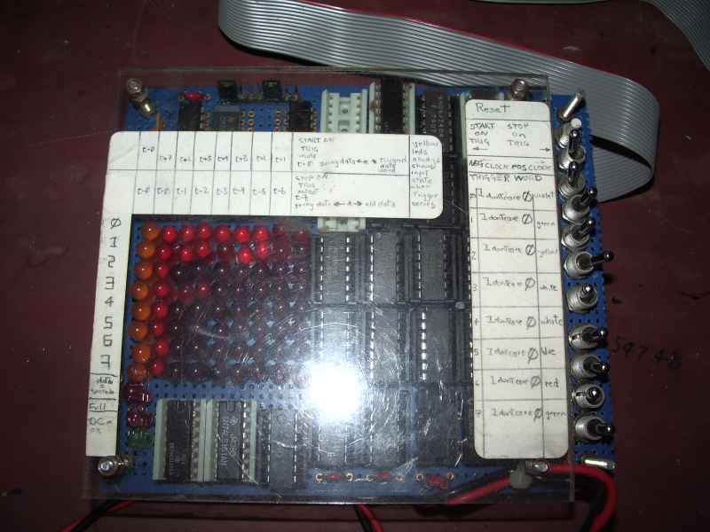
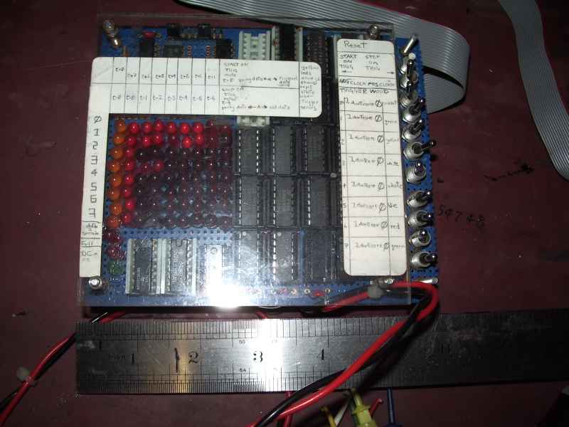
This LSA design is based on nothing more than an true-false-dont-care
condition detector and a memory and display system based on nothing
more than a few serial shift registers. The design has a
basic flaw rendering it unsuitable for most synchronous state machine
debugging, this was my fault for not understanding synchonous logic
properly at that time. What was the issue ? The shift registers
clock source should be derived from a gated external system clock , not
from the trigger itself. (bad boy) . The trigger circuit can trigger on
any 8 inputs as 1, 0 or dont care. One register displays the captured
trigger word. The shift registers display states 8 steps before or
after the trigger condition is matched.
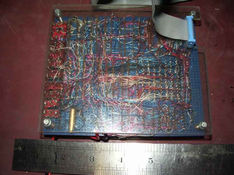
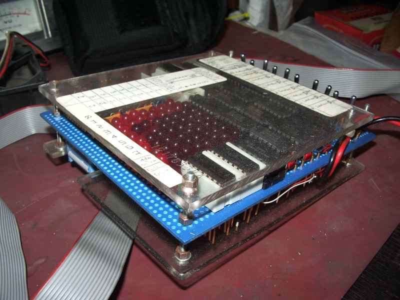
Advanced digital hobbyist may actually find elements of this design usefull. Hobbyists may like to note that the square LED wires actually make satisfactory wire-wrap terminals. 74LSxxx series logic will directly drive a LED hi without ballast resistors. The resulting voltage level is unsuitable for cascading to a subsequent TTL input.
Advanced digital hobbyist may actually find elements of this design usefull. Hobbyists may like to note that the square LED wires actually make satisfactory wire-wrap terminals. 74LSxxx series logic will directly drive a LED hi without ballast resistors. The resulting voltage level is unsuitable for cascading to a subsequent TTL input.
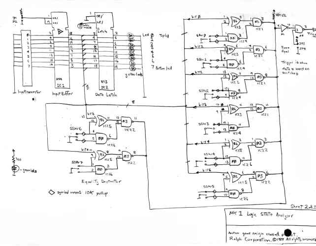
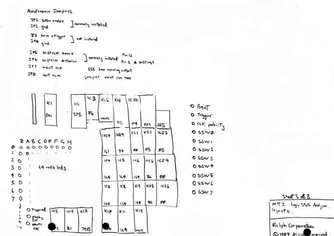
The input signal are buffered
and also fed to a level triggered latch, the latch is derived from the
trigger qualifier. This is biult from the XOR, NAND and open collector
NAND so as to provide a negative level when any of the trigger
qualifier bits agrees with the input and switch setting. The
switch setting permits the qualifier to trigger on ONE, ZERO or DONT
CARE in which case it does not trigger. I strongly hold that a test
instrument should be able to test itself, so a jumper and gate is
provided to force a diagnostic trigger at the test point.
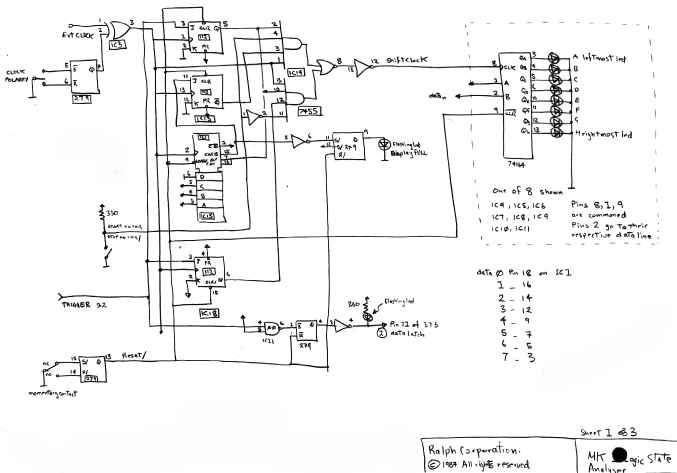
The display controller
The
user controls are start-on-trigger or stop-on-trigger, with the trigger
word being latched in the input display latch. A four bit counter
counts 7 input clock pulses to alternatively block or allow clock
pulses to the display shift registers. The display is based on 8
bit shift registers. The 74LS164 outputs permit you to drive a
LED hi without the normal led ballast resistor, as the TTL totem pole
outputs are inherently current limited to about 20mA when driving HI.
What an amazing coincidence. Just what is required for turning a LED
on! The resulting level is no longer suitable for cascading to other
TTL inputs, so if you must reuse such a signal a seperate LED driver
still is required. The H55 AND-OR-INVERT gate selects the appropriate
shift register clock for the stop start mode selected. A flashing
led is driven by a simple SR flip flop to indicate that a trigger
condition occured.
LEDS have a lovely square pin terminal that
permits you to wire wrap them directly. Who would have thought LED
makers could be so kind! Every other discrete component have cheaper
round lead wires. I wonder why they choose square wire?
Not indicated on the schematic is provision for a 74LS590 tristate 4 bit counter for on board diagnotics.
My device also had polarity protection relay on the main 5V logic supply.
My device also had polarity protection relay on the main 5V logic supply.
