An RF Milliwatt Meter using the |
| Analog Devices AD640 Logarithmic Amplifier |
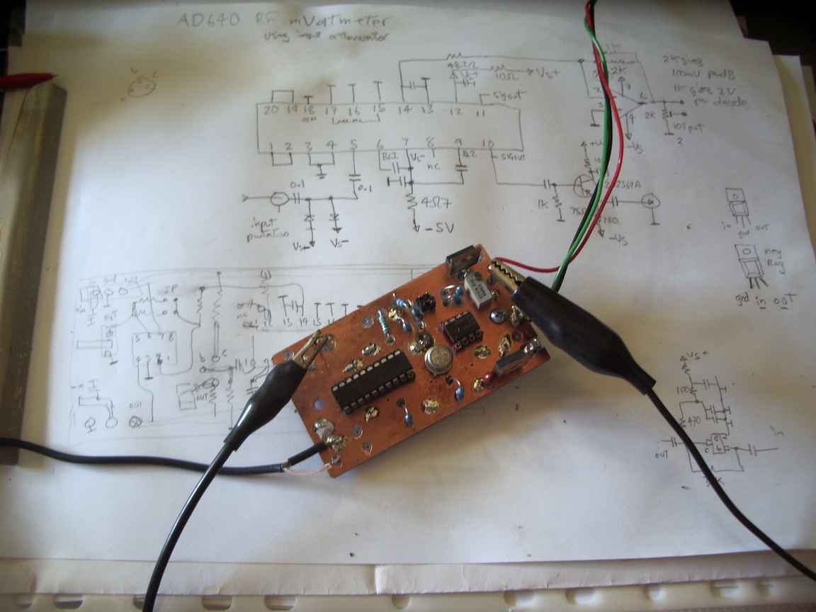
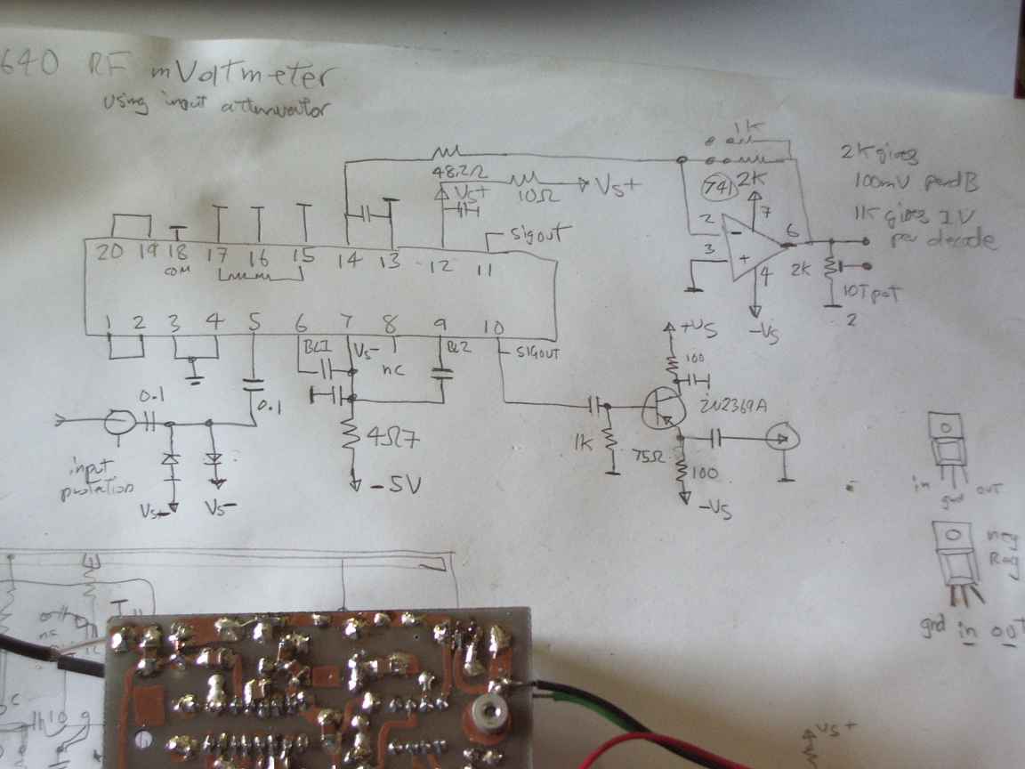
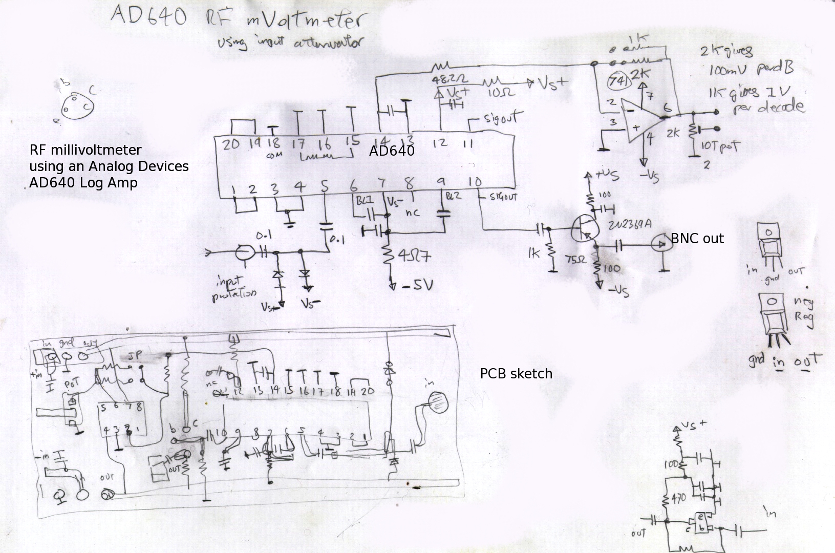
The analog devices AD640 is a low noise high bandwidth logarithmic amplifier that steps up millivolt level RF signals into the logarithm of signal amplitude. It is sensibly linear over about 3 decades of power and can reliably measure up to VHF rf levels from about 40mV to just over 1 volt, something that is nearly impossible with simple rectifying instruments. This design is lifted straight from the Analog Devices application notes, my only additions are reversed biased input protection diodes and a high bandwidth common emitter buffer on the output, to permit driving things like digital frequency meters from small signal sources. My primary motivation for this little project was a broadband amplifier with which to perform bandpass filter alignment in circuits where only milliwatt level signals were present, and also to be able to get reliable low signal power measurements for testing things like balanced mixers. |
 |  |
 |  |
| homemade PCB | |
 | |
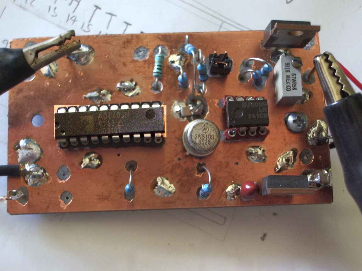
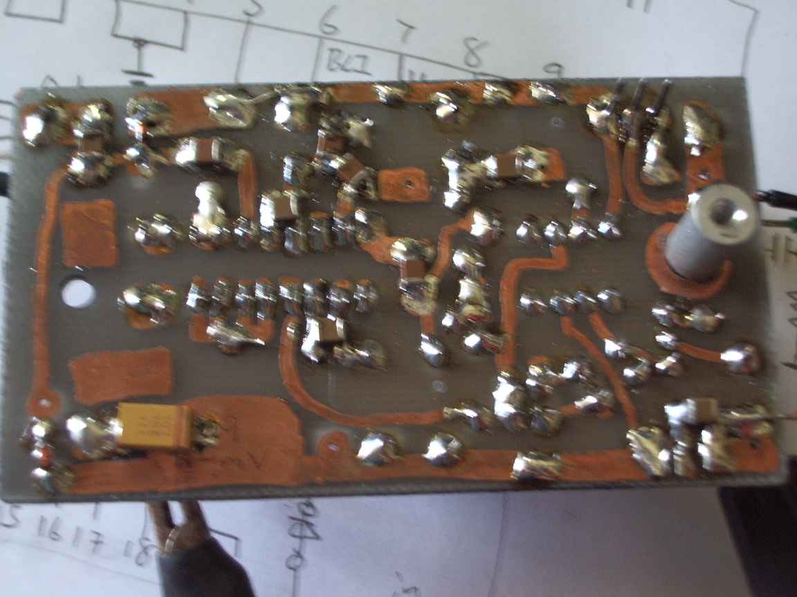
This project must be made on dual sided PCB. The high gain and bandwidth of the AD640 will result in parasitic oscillation unless the inherent sheilding in a dual layer PCB is used. Low profile socket strip was used for the AD640. I thought it was justified, this chip is very costly. Many bypass capacitors were required, all my chip capacitors were recovered from dead appliances by removing them in bulk using a paint stripping gun. The circuit board was made using, not an etching resist pen, but an overhead transperancy marking pen. These pens have a nice thick opaque ink that satisfactorily resists the action of an air agitated ferric chrolide bath. Thse pens are much cheaper than an etch resist pen and work and handle better. They permit both fine and thick traces to be drawn without pain. Those who use etching pens know exactly what I mean. It is easy to do by hand, but first scribe a grid of 0.1 inch lines where the IC pads are to go and "centre punch" using your scriber. This will ensure that when you drill the board, the drill bit does not wander uncontrollably. Clear the copper from component through holes on the other side with a dremel bit. Dont forget, that when drawing out the copper circuit with an etching pen, you are drawing the mirror image, some mental adjustment is required. (wailing and gnashing of teeth will result unless this advice is heeded!) No alignment is required, but I provided a trimpot so that the output op amp can drive any junkbox meter. Only drawback is that the AD640 requires a balanced split DC supply. |
