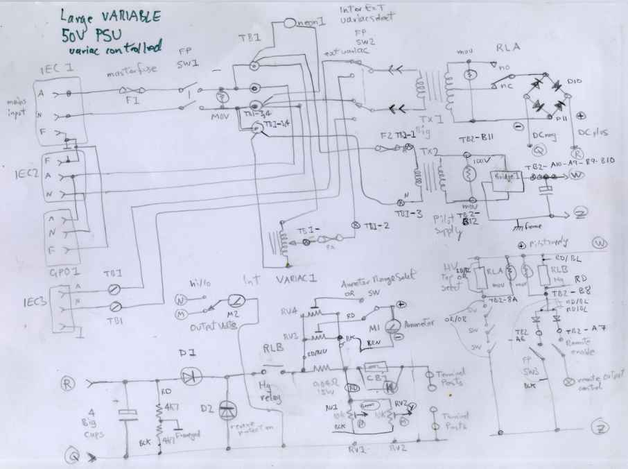
A large variable power supply using a VARIAC as the control element.

by ralph klimek VK3ZZC  March 2011


This project was created to permit me to experiment with MOSFET RF power amplifiers. I wanted something that was continuously variable from near nothing to as high as the main transformer , about 70 volts, would permit.  It also should be capable of at least 10 amperes output at any voltage in its range.

There are any means of producing this outcome however I did not want to have the trouble of designing a boost-buck converter. A switchmode converter of this range of voltage from say 12 to 70 volts is not trivial to design.  I had in my junkbox  this very large transformer with a 35-0-35  output. The large core would allow this to continiusly handle 500VA.  The output should be remotely switchable at any setting. It should also safely shut down under a gross shorted condition.

I also biult this to demonstrate  that a classical  full-wave-center tap or classical bridge rectifier  supply could be fed from a variac.  Everything I required for this project was found in the junkbox.

The internal variac is only rated to 2A intermittant, 1.5 A full current. However due to the magic that is a transformer the secondary output current can be nearly ten times this without adversely impacting the variac !

In operation, the output voltage varies very smoothly and controllably with the variac.  The regulation and ripple, as you would expect, is not great without any true electronic feedback and control, but for my purposes is adaquate for powering large amplifiers.


There is a large contactor type relay for selecting the secondary tap, allowance for an external variac to permit a full 20A at 70 volts, a mercury relay on the
output is capable of switching the full load , at DC.  This is impossible with a conventional relay as it would just arc and melt. Another benefit of the mercury relay is that it is , by default, open circuit. It means that in the event of some catastrophe, it can be relied upon to disconnect the load.
I have another use for mercury relays here.

An internal use only auxilliary supply give operational voltage for the two internal 24V relays.  There is also a very substantial DC circuit breaker on the output that will trip at 20A.  DC rated breakers are as rare as  rocking horse dung.  This one was a relic of my days of computer mainframe service and lay in my junk box for nearly twenty years before finding its second life here.  There is also a MOV across this circuit breaker.  This kind of breaker can induce a mighty inductive surge as they contain a magnetic armature that releases the springs stored energy as an inductive electrical spike. Just what your test projects want !   Use AC rated magnetic breakers with caution on DC.  The DC current will trip the magnetic circuit long before AC will.  An AC arc will extinguish itself if the path length is long enough.  A DC arc can maintain itself in air nearly 10 time longer than an AC arc.

The tap changer interlock consists of  3 front panel switches that must all be thrown to permit the tap change relay to activate.  This was done
to prevent accidental tap changes under load which could be bad for the rectifiers, the load and may cause the relay to arc over.

The output current monitoring shunt resistor is a very rare 0.04ohm Dale resistor. Our old mainframe used to have hundreds of these and I had but one left in the junkbox.   It is basically a short circuit within  a mineralised plastic body.  I dont know what part of this resistor is 0.04 ohms. Surely the leads, alone would have this order of resistance !

Input protection consists of a fuse of last resort, magnetic circuit breaker and MOVs on both the primary and secondary. I believe in MOVs, you should too.
MOVs work better than clamp diodes across relay coils as they permit the magnetic field to decay faster than a diode will permit.


project-variac-large-50V-psu-2008.jpegf
50V 20A variac control variable PSU


thumb.imgp3685-big-psu-variac-2008.jpgthumb.imgp3686-big-psu-variac-2008.jpgthumb.imgp3687-big-psu-variac-2008.jpg
front panel power switches control mains input, int/ext variac select and output controlat the rear are auxilliary mains power connectors and external variac inputthe variac is visisble here under the heatsink. some cooling is desireable
thumb.imgp3688-big-psu-variac-2008.jpgthumb.imgp3689-big-variac-psu-2008.jpgthumb.imgp3690-big-variac-psu-2008.jpg
the main transformer, meter calibration pots and just a hint of the seperate auxilliary control PSU50A amp stud diodes provide for reverse polarity protection and inductive surge clamping. also visible is the output control mercury relay, the little black tube upper leftfront panel controls permit remote control, hi/lo meter range and interlocked selection of centre tap or full secondary via a large open contactor.


homepage

email.jpeg

mod-record.jpg page created Wed Mar 23 19:57:08 EST 2011