Wide
range LF to HF and low VHF sweep generator.
Uses a linear sweep with
independantly set DC baseline and peak controls
Using ECL logic and ECL vco
chips and analog computer concepts.
by
Ralph Klimek 1998
The motivation for wanting a sweep generator in the first place come
from my occassional need to align IF amplifier strips and the
occassional wide band filter. I wanted something "simple", a very
linear sweep, sweep end points that could be precisely defined. A side
feature was to be a sawtooth generator with linear sweep whose DC base
line and peak amplitude could be set independantly, unlike simple
schemes that define the sweep in terms of offset and gain.
I wanted to satisfy the following design criteria.
- simple
- reproducible behaviour
- non exotic components
- LF through to low VHF coverage
- linear sweep
- sweep endpoints to be independently settable
- sweep endpoints had to be callibrated with external
frequency counter
The final outcome
satisfied some of these criteria!
The design cannot be
reproduced
because it is now impossible to obtain the MC1658 vco. In any case,
modern design would use a combination of PLLs and direct synthesis and
microprocessor control. Its allmost impossible to source ECL
logic in this day. This should be a cause for great sadness.
The motivation for this
particular
implementation arouse after acquiring some discarded PCBs from
old fashioned washing machine sized disk pack drives. The
analog
boards also contained a large amount of Motorola MECL MC10xxx logic.
There where some MC1658 wide range VCO chips as well.
These
remarkable devices can be made to oscillate from VLF to VHF with one
control voltage and requiring you to change only one timing capacitor
to give over two octaves of vco control. The chip is based on an ECL RC
multivibrator and as such has a large noise bandwidth, much larger than
an LC and varactor design. The classic L C and varactor design has
typically only half an octave span. The large noise bandwidth
was
not a concern for me as I would be alligning only LC bandpass
filters.
ECL is a much maligned
logic family.
It does not deserve the bad press. Motorola ECL has been around since
the early sixties. Sadly they only sold their output to "black"
millitary buyers and by the time Motorola has licensed the technology
to NEC and others, Texas Instruments had the whole world hooked on
their totally inferior 74xxx TTL logic family. clever
marketing
arms had it put out that ECL was "too hard" to design with. It is a
great pity that early eighties minicomputers were made with 74Sxxx
seris logic instead of MECL. Had they used MECL they would have had 10
times the mippage at near zero additional design cost. Seymour Cray had
seen the light, the CRAY1 was made from MECL gates
and the major governments of the world beat a path to his
door.
ECL is EASY TO DESIGN
WITH. No ifs
and no buts. Simple fan in and fan out rules, every gate output is a
line driver, every node is a transmission line (that must be terminated
at both ends). A good ECL gate can toggle at least 100Mhz (mid sixties
technology here, the best mid sixties commercial logic RTL could barely
toggle at one megahertz). The last generation
MECL111 could
easily do 400Mhz in a 16 pin DIP (with a little bit more care to be
fair) The only valid objection to using ECL is that it is
very
power hungry, that much is true.
I would use MECL to
first generate my
signals and MECL logic to move it about and switch it. It takes a true
tried and tested electronic engineer to get 74Sxxx logic to do anything
usefull at 50Mhz but a mere technician/tinkerer like myself can make
MECL sing and dance at 100Mhz.
In this design I reused the many MECL gates that I salvaged.
The heart of the design
is the linear
sweep generator. The ramp is generated by the tried and true method of
charging an integrator from a virtual constant current source driven by
a voltage reference chip. At the end of the charging cycle the
integrator capacitor is discharged by a mosfet.
The integrator reset signal is generated by a comparator that measures
when the ramp has reached the desired level. This
reference
level can be switched to directly drive the vco level permitting the
span of the sweep to be directly "dialled up" on a an external
frequency meter. A calibrated DC offet signal is added to the
ramp before the reset comparator. This offset voltage may
also be
switched to the vco so the base line or "zero" frequency of the sweep
may also be directly "dialled up" from the ten turn pots on the front
panel. There is no interaction in these settings! Unlike the usual
mutually interacting adjustments of gain and offset method.
Some
designers may have picked out the fact that by doing the sweep
endpoints this way I lose a measure of control over the sawtooth
period. As this sweep generator is meant to be used with a
compainion oscilloscope, this is not objectionable because the sweep
generator also provides a nice horizontal sync pulse, so the actual
sawtooth period is not that important. The comparator,
however,
provides only a comparison level, not a pulse, and the integrator must
be reset with a pulse. A simple monstable provides a good
narrow
reset pulse. For initial debugging and testing dip switches
select the reset pulse polarity or a 555 free run pulse .
I have chosen 5
differant and
slightly overlapping sweep ranges. These are created by three MC1658
vco chips, the lower frequency ranges being selected by adding timing
capacitance with relays. The highest ranges are very sensitve
to
stray capacitance, so relays could not be used, instead a dedicated
MC1658 was used . The outputs are selected and routed by ECL logic
gates.
A reference counter generates 10M, 1M and 100Khz calibration pips which
are mixed with the generator output with an MC10107 XOR gate, the
output DC smoothed and displayed on the secondary oscilloscope channel
to provide a graduated "pip" display. Unselected MC1658s are
handled by driving an internal voltage reference decoupling line to ECL
Vee, this is not the intended use of this pin, the chip has no
deliberately designated "chip select" signal. I disable unselected VCOs
so that they dont free run and generate spurious signals, a trace of
which may reach and contaminate the output.
Frequency range is
determined by a
simple rotary switch that feeds a priority encoder to generate a
binary control word. The various logic control signals are
derived from this control word and 74151 muxes to create the abitary
unary logic control signals from this control word. This arrangement
permitted me to corect errors in logic design by simple re wiring
rather than by a complete redesign. (also known a microprogramming in
more elite circles)
Second thoughts.
The ramp generator could
have also
been implemented using a variable precision clamp and followed by
a variable gain element. The ramp period could then be
independantly set. it would have been difficult to provide a set level
for the gain element to permit setting the sweep endpoint with an
external counter. Doing so would have required four-quadrant
multipliers which are a pain to design , calibrate and use. The
MC1658 VCO is really an RC multivibrator with a controlled current
source feeding the internal timeconstant. As a result, this oscillator
has a rather high noise bandwidth, it would be much lower if real LC
resonators were used in a standard varactor controlled VCO. As it is,
this sweep is satisfactory for tuning wide band filters, but useless
for narrow band applications like setting up crystal filters. The ramp
generator has proved to be very successfull.

individual vco sweep oscillators, signal selection, vco selection and
marker pip generation

control logic, rotary switch drives 74148 priority encoder, binary word
decoded by 74151 muxes

The ramp generator

misc notes to myself

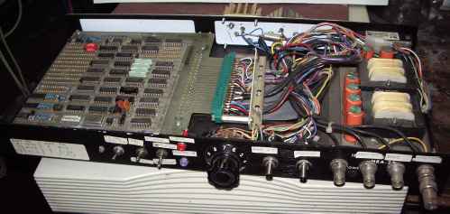

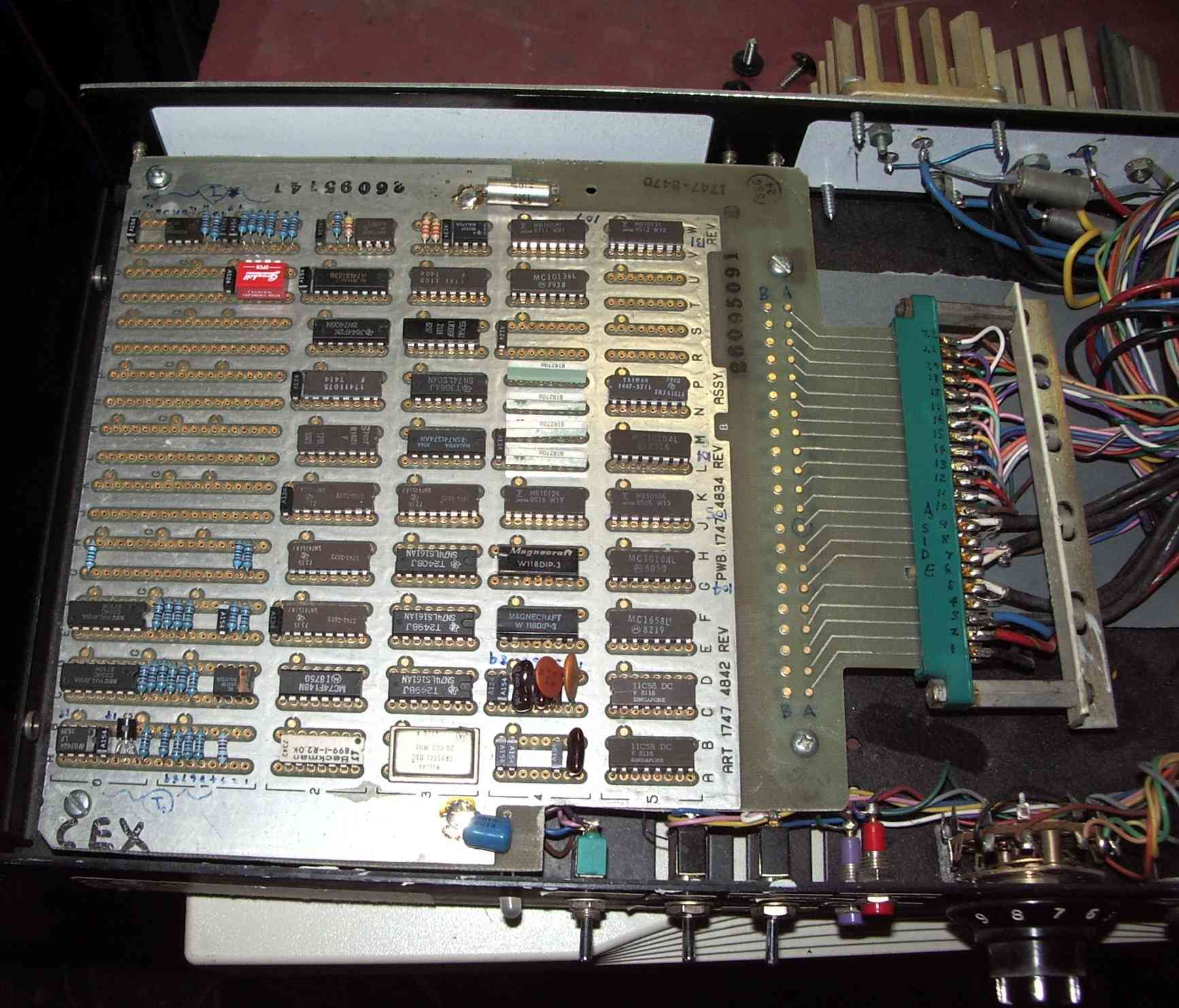


constructed on wire wrap cards recovered from a Burroughs B340 seris disk pack drive controller

