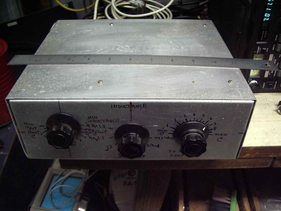
The ARRL transmatch
as implemented by ralph klimek aug 2009

This is not an inovative design at all.  Its just another implementation of the good old ARRL transmatch design, popular because you do not require the now impossible to obtain (and unaffordable) roller inductor.

I began this project in 1974.  I had just moved into a new house and was wondering the neighberhood to get a feel for the place. There was a local council hard rubbish collection where the the good burghers of Melbourne are encouraged to dispense with their surplus goods and chattels by leaving them out for removal and curious passers-by.

I passed by one pile of junk and noted that it contained the remains of some piece of military radio equipment.  It has been heavily cannibalized and only a few of its components had remained. I knew nothing of military equipment back then or what this radio was or its history, only that it was junk, unrestorable and for me , merely a source of hard to get radio components.
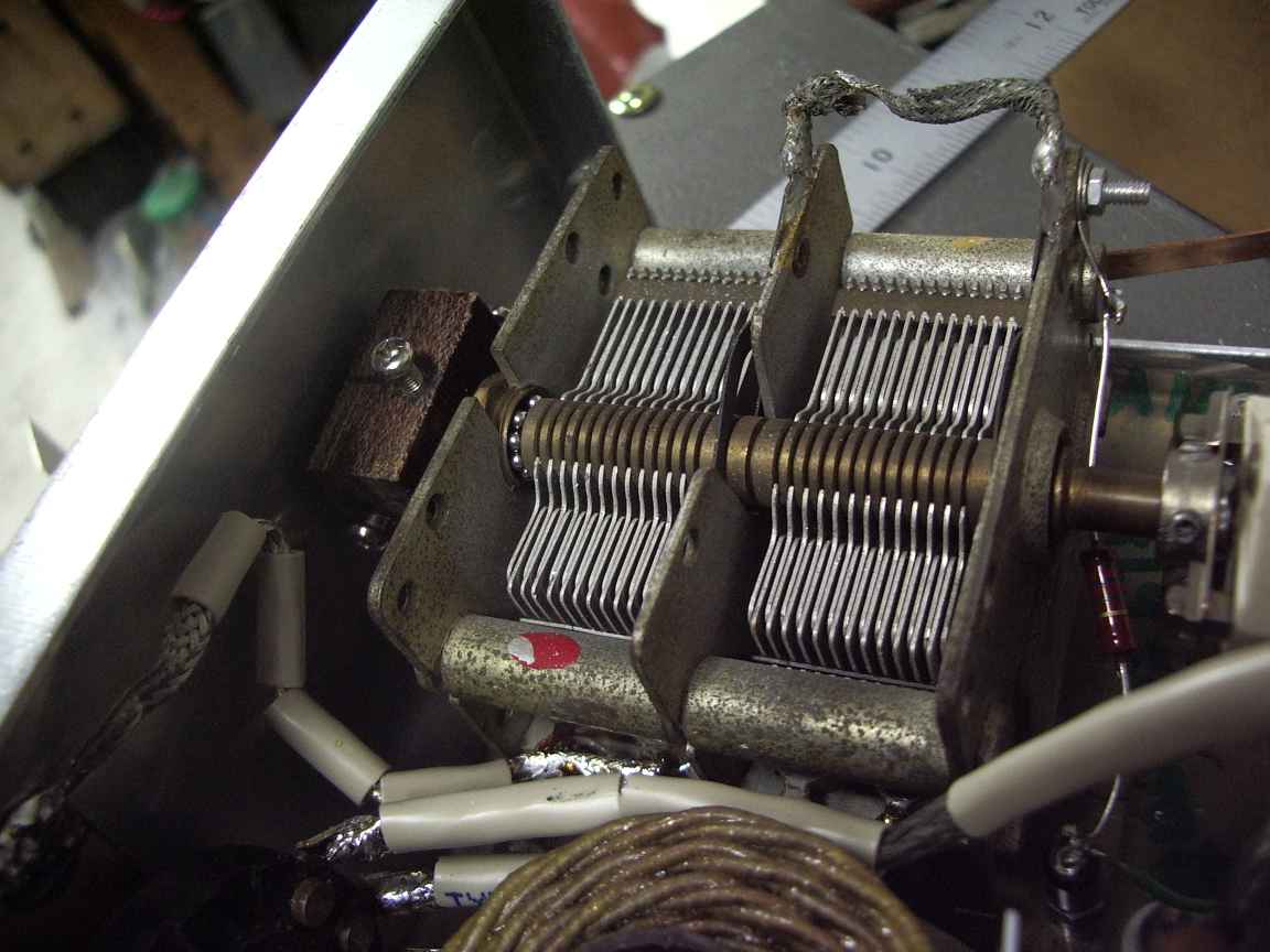
The radio set in question, as I learned decades laters, was the famous Radio Set Number 19.  All of the remaining components that I had laboriously removed from it  had been slowly used or lost in the decades since that rainy winter afternoon except this variable capacitor.
I kept it because it had ceramic insulators and I knew enough electronics at this early age to know that this was a good thing. The capacitor had a shaft that continued out the back,  and two full bearing races.  The normal broadcast tuning gang had only one ball race and only the one shaft.  I knew that this had to be usefull for something !

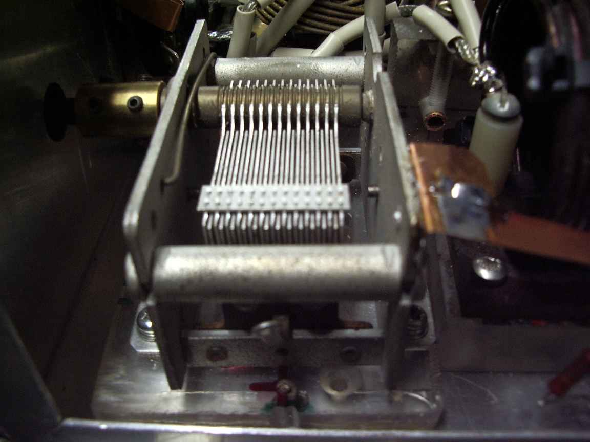
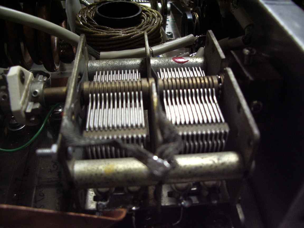
That something was to be one arm  of a DIFFERENTIAL split stator variable capacitor, rendered tractable by having the shaft coming out both ends.  It could be mechancially coupled to another broadcast gang in such a way that as one capacitor increased its capacitance, the other would decrease .  This can, and is used in the transmatch circuit to serve as both a variable reactive element in a tuner and as a fully variable impedance tap, think of it as an variable capacitive autotransformer  (variac anyone ?).   With such a device in resonance with a parallel tank inductor it is possible to  tap down any and feed (or source)  any  resistive impedance.

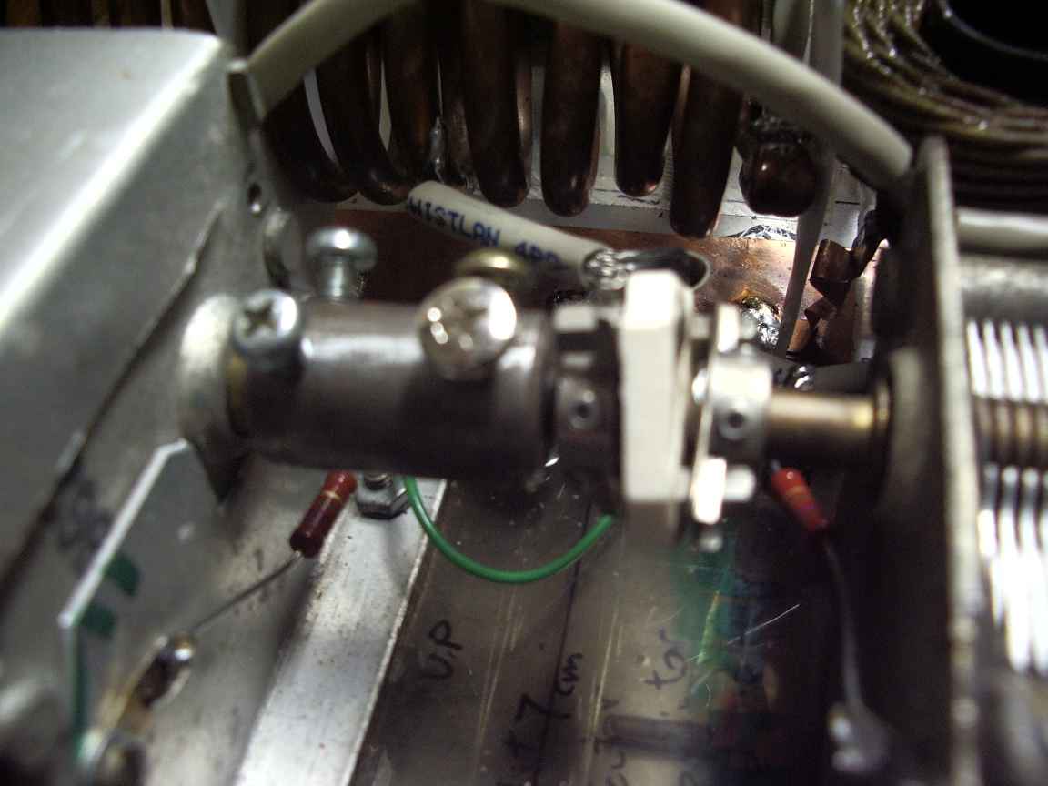
You can see the old capacitor now in service again, after lying idle for 60+ years as one arm of my differential capacitor. It is electrically isolated from its companion capacitor  by a ceramic shaft coupler and both mounted on a sheet of perspex.  I do not force RF currents from the capacitor rotor wiper. I dont think this is a good thing. The circulating RF currents are quite high and I do not trust the old wipers in this duty. Instead, I feed the RF current via both stator  sections, effectively putting the two capacitor halves in series, doubling their total RF breakdown voltage and forcing the RF current to travel via the rotor shaft and avoid the wipers alltogether. This has to be a Good Thing. It affords a serious improvement of the tuned circuit Q.  Allways use a proper shaft coupler ( universal joint ) for coping with the lack of colinearity of the capacitor shafts. No matter how skilled you are at metalwork it it impossible to get the two shafts perfectly collinear.
The capacitance of each section is normal 415pF, in series is half that  which is exactly what the standard transmatch design requires.

The capacitor frames are effectively floating for RF, thus avoiding parasitic resonances. I do ground, via some 1M ohm resistors the capacitor shafts, and frames , for the elmination of static electricity. I did this to raise the flashover potential of the capacitors because they were never designed for transmitter use having a plate seperation of about 0.5mm.  It would not be hard to accumulate 1KV of static charge that would iniciate  an RF flashover, so just get rid of one potential source of flashover.  My guess is that this arrangement will make my
transmatch safe for power use up to between 100 and 200Watts and maybe more with a well matched load.

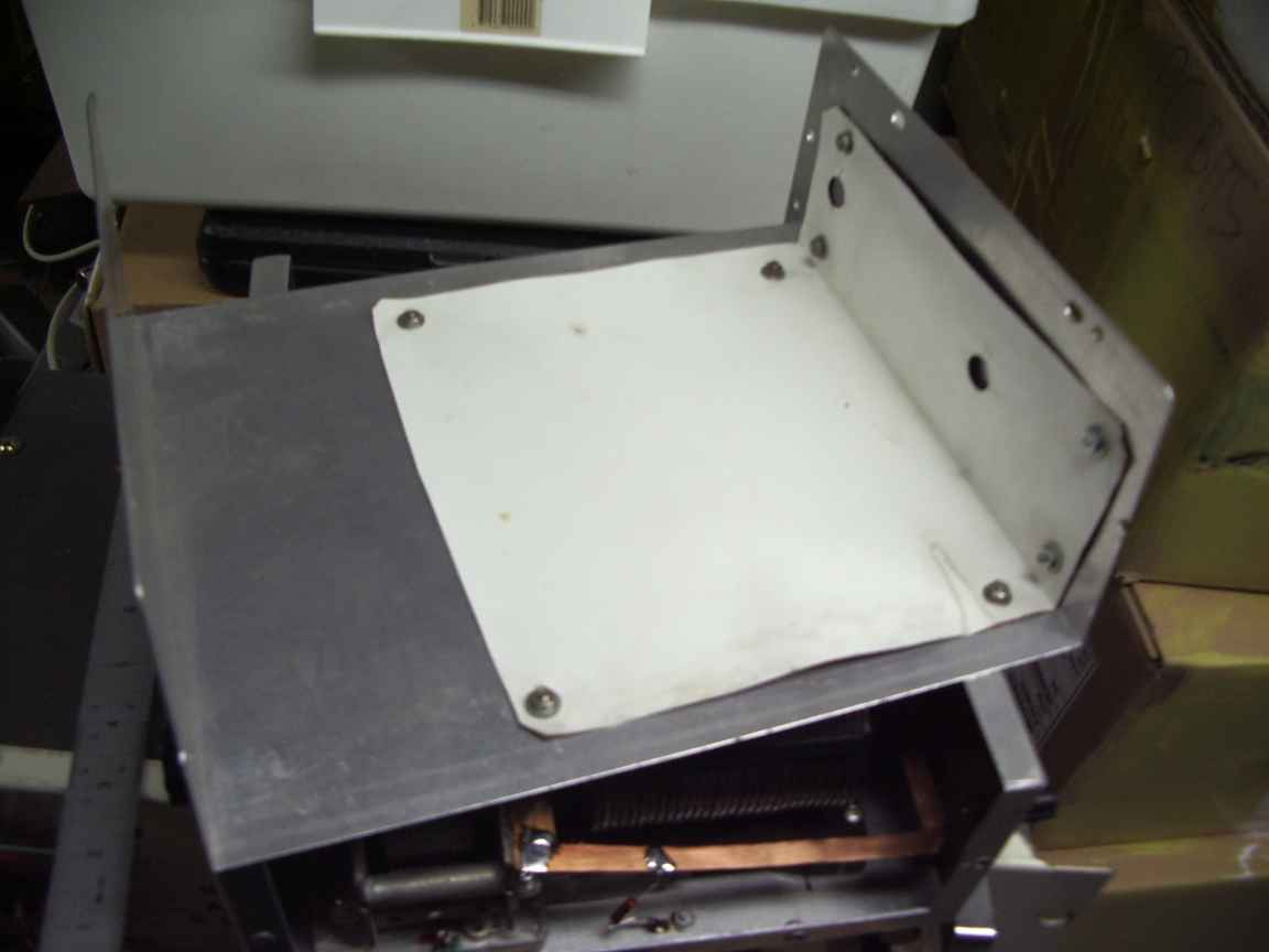
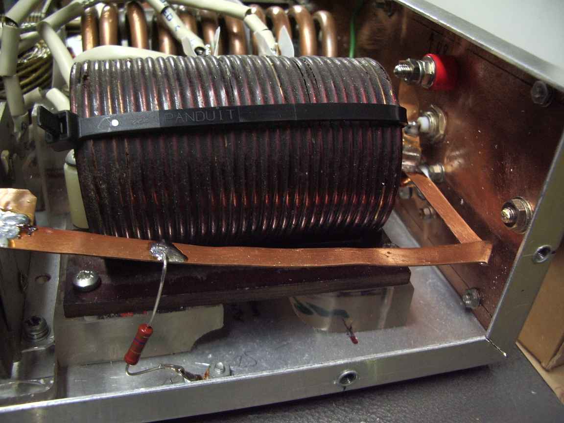
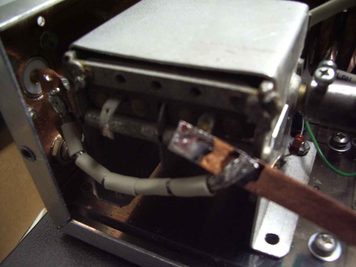
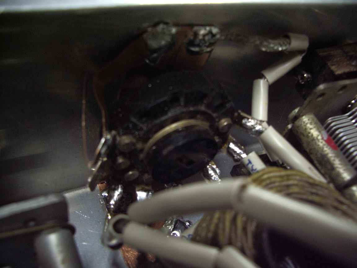
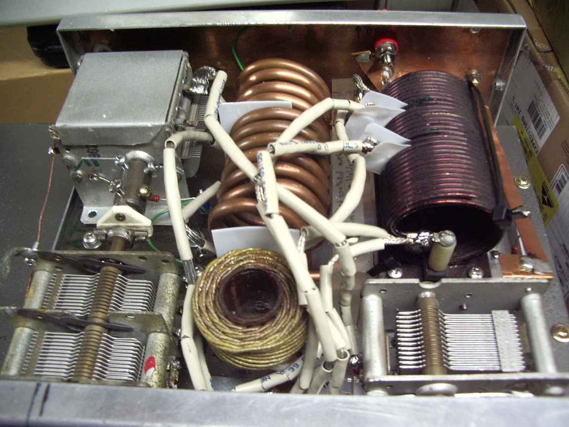
The only refinenment in my implementation is the use of copper sheet metal for creating real soldered RF grounding points. Dont think for one millisecond that you can create a good low impedance RF ground by grounding to Aluminium with a grounding lug and screw. It just wont cut it for RF.  It is actually very difficult to connect to Aluminium, especially at RF.  I got my copper sheet metal from a discarded copper hot water service.  Double sided PCB would also work well. Soldering to copper sheet is easy, but you really do need a gas powered iron, at least 100 watts.  Underneath the small inductor (not visible here) is a large copper strap that forms the positive RF earth for the tap shorting front panel selector switch and input capacitor.  Do not rely on RF current reliably going through the switches rotating shaft to chassis.

Dont forget that the variable capacitor shafts are live with RF, you must use plastic rods to couple them to the tuning knobs.

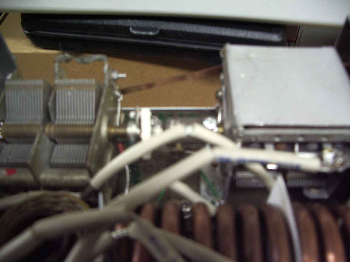
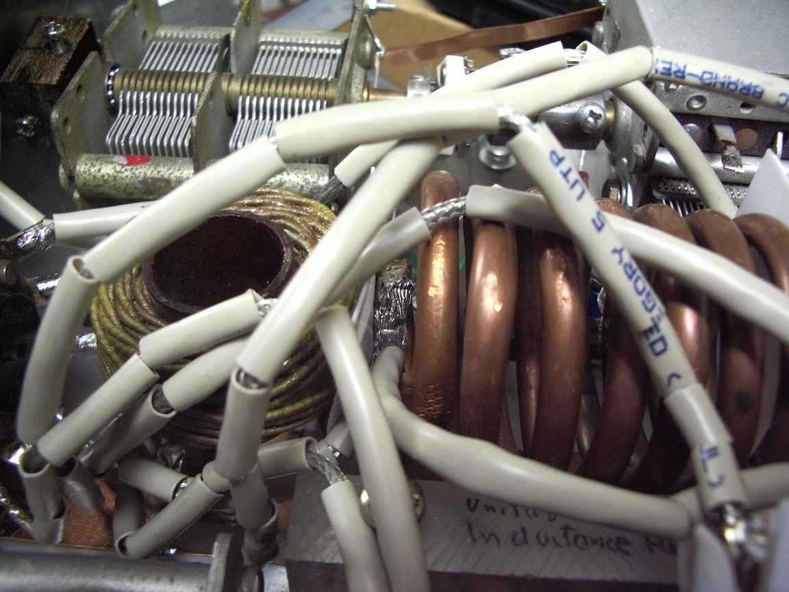
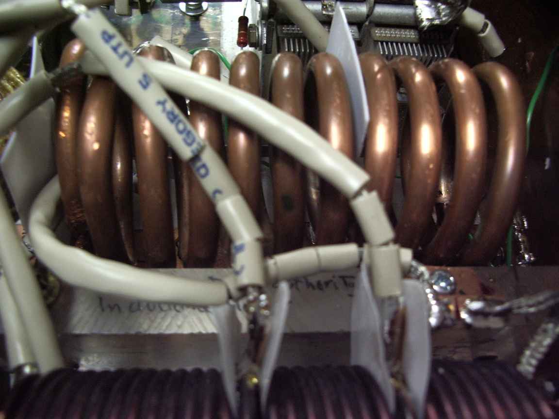
The inductors in my transmatch also have a slightly less colorful history.  The low inductance coil is a copper heat exchanger I found in an industrial waste skip made from quarter inch hydraulic copper pipe. The medium coil came from a Burroughs mainframe power supply switchmode regulator, I just added extra taps. The taps are sheilded with teflon sheet to prevent shorted turns.
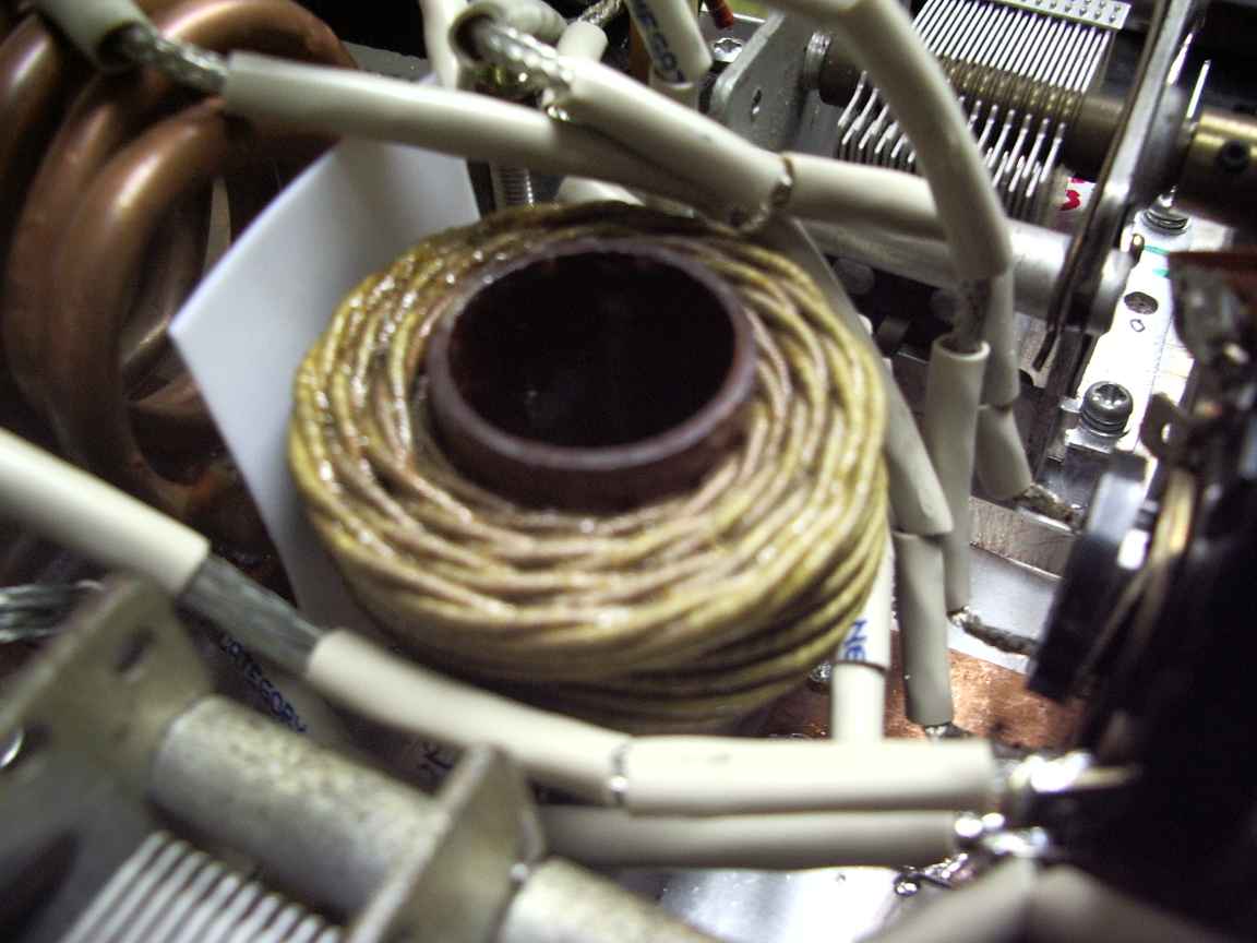
The high inductance coil came from the surge current limiting coil from the capstan drive of a long forgotten Burroughs tape drive. I knew that I would find a use for that coil, I kept it because I cannot do the PI winding by hand.  I had to wait twenty years at the bottom of my deepest junk box where it served its duty as a retirement home for large angry  ugly elderly deadly ghastly red back spiders!


Internal conductors are either copper strap cut from a sheet of copper flashing or the outer braid stripped of from heavy duty RG58. The heavier the better. RF loves thick conductors ! All RF joints should be real metalurgical joints, solder everything !

One thing that allways puzzled me about the ARRL transmatch was the use of selecting taps by shorting them to ground. I thought,
isnt that making a shorted turn, and isnt that bad ?  One advantage in having multiple coils is that the magnetic flux one one coil is not sensibly shared by other coils. But what of the same coil ?  Because these are High Q inductors, the resulting circulating currents are not readily dissipated. It becomes a scenario of putting coils in parrallel, which reduces inductance. The other rational of shorting the non selected coils is to reduce the possibilty of exiting parasitic resonances. Common sense suggests that there are just as many potential parasitic resonances in a shorted coil as an open one, except that they would occur at higher frequencies, hopefully well away from the intended usage frequency.  I have yet to check mine with a grid dip meter to see where the parasitic resonances occur, but they do exist. The laws of physics demand it.  I have also added a sheet of copper flashing the to lid.  The box I used was some surplus junk, it was just the right size, and I think a little too small. High Q solenoid inductors really should have lots of free space around them, because free space does not dissipate energy. If you cant have free space, then, the confining metallic surfaces should have the least resistance possible and that means copper.  In an ideal world you would make the box out of silver metal or copper sheet but we do not have access to Defense Budgets ! (or live in an ideal world)


But does it work?  Yes!

thumb.imgp4522-transmatch.jpgthumb.imgp4524-transmatch.jpgthumb.imgp4523-transmatch.jpg
the completed transmatchtaps on the medium inductor. a piece of teflon is removing a self inflicted shorted turn.top view, copper backplane for positive RF grounding
thumb.imgp4537-transmatch.jpgthumb.imgp4535-transmatch.jpgthumb.imgp4536-transmatch.jpg
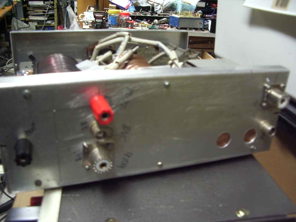
top cover with copper flashing shield near the inductorsdifferential capacitor at 2/3rds meshthere was space so I put in both PL259 and  BNC and terminal posts
thumb.imgp4525-transmatch.jpgthumb.imgp4526-transmatch.jpgthumb.imgp4527-transmatch.jpg
antenna output capacitor.output strap is soldered to capacitor frame. I will take my chance with the  rotor wipermedium inductor and output strap, static drain resistor"high" inductor
thumb.imgp4528-transmatch.jpgthumb.imgp4529-transmatch.jpgthumb.imgp4530-transmatch.jpg
after 60 years , a No 19 set tuning dual shaft capacitor finds a new jobhomemade sharft coupler and universal jointupper differential capacitor
thumb.imgp4531-transmatch.jpgthumb.imgp4532-transmatch.jpgthumb.imgp4533-transmatch.jpg
another view of the venerable capheavy duty tap selector switch from an old electric blanket controla tangle of tap conductors made from heavy RG58 braid


note-to-self    insert schematic diagram here


thumb.transmatch-schematic.jpeg


copy right declaration
this article, images and text is copy-left. You are free to reuse them as you see fit


HOME PAGE

mod record
page created at Tue Sep  1 18:17:04 EST 2009

email.jpeg