this article is copyleft, contents free to be used for all honorable purposes
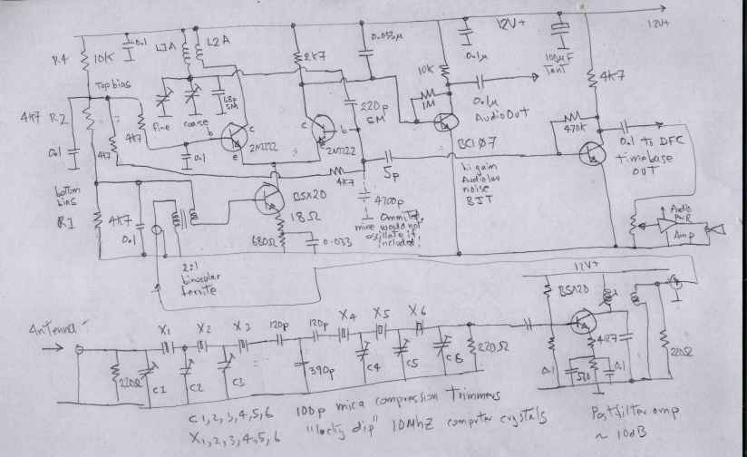
Presented here is a remarkable design for a homodyne receiver that self locks and demodulates the time and frequency transmissions from my favourite radio station WWV. The purpose of this project was to replicate the experience of WA5BDU K7Q0 VE3DNL (see below) whose simple 5 transistor homodyne receiver is claimed to lock on to WWV, allthough the primary purpose of that design was to be a simple receiver for 30 Meter ham band. In the mainland USA, one would expect to receive an overwhelmingly strong local signal from WWV. On the other side of the planet here on the bottom end of Oz, the signal is good, mostly good in fact but hardly enough strength to be considered usable as a timebase. There is severe interference from digital appliance garbage . A homodyne receiver will spontaneously lock on to the strongest carrier within its lock range and passband. If it locks onto WWV , the self oscillation frequency will be a faithfully replica of WWV's atomic clock allowing for the ionospheric phase distortion , then I should expect 1 part in 10^9 from my receiver in this part of the world. My modifications to WA5BDU simple design include a 10Mhz LSB crystal ladder filter to ensure that the only signal around will be either WWV WWVH or the local Chinese governments standard signal.
With the signal for WWVH measured at my location from the big antenna at an average of -80dBm, this receiver achieves a homodyne lock and a rock solid lock at -70 dBm. This gives me access to a NBS accurate timebase for about 7 hours in a day, if the lords of the ionosphere permit.
The action of the crystal ladder filter is quite amazing. The main antenna picks up nearly -30dBm over a spectral range 3Mhz to 20Mhz of radiated garbage from my neighbors plasma screen TVs. This cacophony of garbage provides for spurious mixing products in my main shortwave receiver a TS780 that render WWV allmost inaudible. When the filter is applied, even allowing for the 10dB insertion loss of my poorly designed ladder filter, WWV become plainly audible.
The little homodyne receiver can pick up WWV via the ladder filter when it is inaudible via a "proper" sw radio. Thats the miracle of regenerative detectors.
My ladder filter leaves much to be desired. Rigorous design requires one to measure each crystal's dynamic equivalent motional reactances and design the ladder reactances to suit. I was able to purchase a bag of 10Mhz computer crystals for a few dollars, so I just grabbed those that resonated closest in frequency. I used mica compression trimmers instead of "designing" the ladder reactances. I just twiddled the trimmers until I could hear WWV. Nasty, nasty nasty ! The penalty I pay for this is high insertion loss and WWV sounds pretty horrible but most importantly it lets the precious carrier signal through and little else which is that which is actually required. The audio signal, horribly distorted by the uncertain group delay of my primitive filter , merely confirms the correct reception and gives good audio indication of a true lock.
I have included an audio power amplifier and little loudspeaker in this radio which was a mistake. The reason that if the volume is too loud it modulates the free run oscillator which results in audio feedback. It also thus compromises the phase stability of the timebase. It works ok with an external speaker.
And now, still to do. This requires a post filter amplifier to give extra headroom so that lock is not lost during QSB fades.
An external frequency control is actually required as the free run frequency has to be within about 15Khz of 10Mhz or lock cannot be aquired with my average -80dBm of WWV. WWV is also available at Melbourne on 5Mhz nearly every evening and sometimes on 15Mhz if the ionosphere permits. I have never heard WWV on 20Mhz and only once on 25Mhz on their new test transmission there. This radio is so simple that I should make one for each of these channels given that cheap computer crystals for ladder filters are so readily available. I have now incorporated a 10dB post filter amplifier that compensates for its high insertion loss.
Should the free run oscillator use a generic 10Mhz crystal rather than a LC resonator ? That is a interesting question.
I think the answer is yes. Proving that lock is achieved would be much harder.
How do I know when lock is achieved ? Monitor the free run oscillator with a counter. It will be at least a few kilocycles off frequency. When lock is acquired it will jump immediately to 10.0000000Mhz or to the audio carrier standard tone sidebands which is not usefull. How to detect this ? that is the purpose of the audio amplifier. When it is correctly locked you can hear the deep 100 cycle subcarrier on which is modulated the BCD timecodes and the voice announcements are correctly demodulated and "sounds right" .
Why did not I just build a GPS disciplined oscillator ? Because that is actually hard to do. GPS receivers only output a 1 pulse per second signal that has an average 50nS jitter because it is generated by software running the GPS algorithms. On long average the 1 pps signal is a good replica of the atomic clocks in the sky, but it is impossible to phase lock to this slow clock. You can only measure and compare averages and thus GPS disciplined oscillators have an aquisition time of the order of 10-20 minutes. The homodyne radio , if it locks correctly , aquires lock in milliseconds. (but still subject to ionospheric random phase shifts).
Rationale
Why did I embark on this little project. Recently I have aquired a HP model 105 quartz oscillator which I have restored to life. I would like to have frequency references accurate enough to attempt QRSS of which one part in 10^9 accuracy in your timebases seems to be required. I have a number of good frequency counters that do not concur in the seventh or eighth digit and so a NBS locked timebase seems to be the only way. I need to calibrate my HP model 105 quartz oscillator and simple zero beating can only get me within about 50Hz of the truth due to poor audio low frequency repsonse. I will be using the method detailled in the various HP service manuals that describe counting the rate at which WWV sine waves wonder across a CRO sceen that is synced to your local timebase. You can get on part in 10^10 achievable without elaborate test gear or atomic clocks.
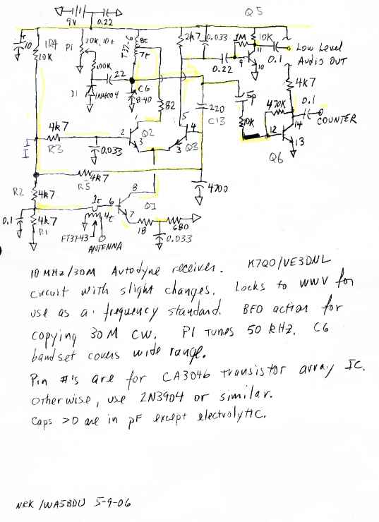
Here is what I based my WWV receiver on . Attribution and thanks due to WA5BDU K7Q0 and VE3DNL
other notes The inspiration and the guts of my WWV timebase receiver are based on the above drawing. I have had to make a couple of modifications and add some extras. My timebase does actually work , but is operationally impacted by my very high ambient rf noise envioronment due to my neighbors' stupid plasma TVs that puts MILLIWATTS of broadband garbage into my main antenna. Happily there is no major spur in the passband of my filter. I wonder if there is enough energy to light a LED ? the 4700pF capacitor on the base of Q2 was removed in my implementation because it would not oscillate with it included. Maybe my choice of 2N2222s did not have enough gain. Dunno. I choose an old BC107 super gain low noise transistor as the first audio amp. This was a good choice as the recovered audio level is low. It came from my junkbox. It dates from the 1970's. They made superb low signal transistors back then too. If you find these of the even better BC109 at hamfests, snap them up ! The British proved that they could do amazing things with semiconductors all by themselves. I also used a good RF transistor for the signal input, a BSX20, which is meant for very high speed switching with an Ft of about 700Mhz. Avoid the use of microwave capable devices here or you will have intractable stability problems. When I made the PCB for this project I deliberately neglected to incorporate the voltage controlled frequency control on the rationale that it would only ever be tuned to WWV. That is still true, however, the natural drift in free run oscillators is such that under low signal conditions we are still required to "ride" the free run frequency to get it as close as possible to 10Mhz before applying the antenna. I will now have to modify my PCB to include the varicap diode as some sort of front panel control is actually required. I had hoped that I could use the trimmers to set and forget, but such is not the case. I would imagine that if you lived in mainland USA you get sufficient signal from Boulder Colorado, but here down under this is not the case. Here in OZ there is a Chinese standard time and frequency service on 10Mhz, which is excellent to have but not as strong as WWV. There is a Russian time sender that is displaced by 4Khz at 9.996Mhz...why why why ? This is still just in the passband of my filter and my oscillator will jump modes to lock on this signal! Ugh ! Is this a cold war remnant ? see also this very usefull website http://www.dxinfocentre.com/time.htm My audio power amp was salvaged/re purposed from a discarded two way radio so I will not tender a circuit. An LM386 would serve well here, otherwise. Would I consider building separate units to lock onto 5Mhz and 15 Mhz. Yes, the 10MHz project has been a success. There exist abundant supplies of cheap "lucky dip" crystals for ladder filters at 5 and 15. And I get good reception at 5Mhz and sporadic reception at 15 Mhz. I was somewhat disappointed in the performance of my ladder filter. This was my fault as I used my lucky dip crystals without checking their exact series resonance and choosing appropriately. Makers of crystal ladder filters suggest buying a dozen crystals and selecting half a dozen closest devices. I trusted to luck, not to design and mostly got away with it. Then there is this idea. How to tune a crystal ladder filter. Put a broadband noise source at the input to the filter. the filter output goes to a single side band reciever. Examine the audio output with SPECTRUMLAB. Tune filter trimmers for best uniform envelope. Mission accomplished. Now why did I not think of this the first time ? The timebase output needs better buffering and squaring. The difficulty here is that these circuits MUST be well isolated from the oscillator or the whole receiver will just lock onto its own output which is useless. To be added, a simple common collector unity gain buffer on the timebase output. The simple class feedback amp does not have sufficient reverse isolation. |
The homodyne principle mixes the incoming RF signal with a replica of itself. This is the basis of many QRP direct conversion receivers . The replica comes from an injection locked oscillator. There exists only a very poor theoretical framework for the operation of injection locked oscillators and my musings with SPICE have not succeeded in modeling the behavior of regenerative circuits like Q multipliers, injection locked oscillators or regenerative detectors. An oscillator can also be thought of as an amplifier with self positive feedback, but moreso. Positive feedback can be modeled and in the absence of some kind of energy restraint, signal will build up to infinite amplitude. An oscillator may be also thought of as an amplifier of neat infinite gain....but only at the frequency of oscillation. Now what happens when we apply a weak signal that is infinitesimally different from the natural free run frequency ? Our oscillator will amplify it to the energetic maximum and provide a substantially amplified replica of the input signal. It begins oscillating not at its preferred natural resonance but at the frequency of the source ! Such an "amplifier" has significant limitations. Its gain is unstable, it reacts non deterministically with its immediate envoironment, also amplifies natural noise and imposes phase uncertainty on the little signal that we are attempting to amplify. It also has limited lock range, it may shift modes and lock onto undesired signals present in its passband.
It has been observed by the clock makers of antiquity that two identical clocks when placed side by side will spontaneously phase lock. The phenonemom was called synchrony.
Here the top two transistors form an emitter coupled tuned oscillator. This circuit will happily oscillate in the complete absence of an input signal. The bottom transistor provides a constant current source and this current sloshes back and forth between the transistors at its free run rate mostly determined by the resonant collector circuit. A tiny signal applied to the base of the constant current transistor now provides an infinitesimal variation in collector current that acts to slightly change the phase of the free run oscillator. The circuit acts to track this phase with the input signal, eventually the oscillator creates a good replica of the input signal.
Our WWV signal is also amplitude modulated with announcements and tones and ticks and this SLOW amplitude and phase modulation will be superimposed on the oscillator emitter currents. It will be switched at the oscillation frequency....in effect it will be acting like a switching mixer. The DC component of this mixed signal is integrated ( low pass filtered) by the collector load circuit capacitor and this has now become our demodulated audio signal. It has been DIRECT converted with an RF signal that is a good replica of the signal being demodulated. This is the homodyne principle as distinct from non phase coherent direct conversion ( as is a simple product detector for cw/ssb)
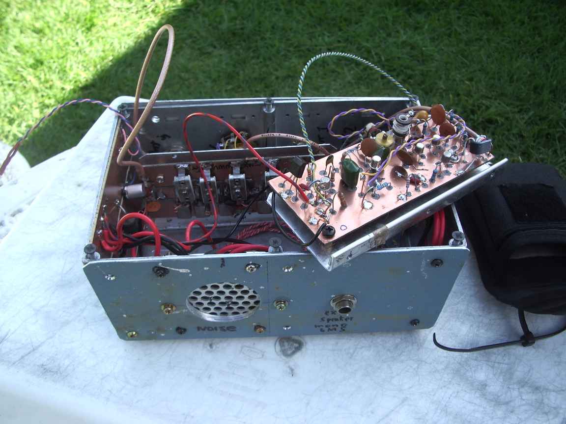
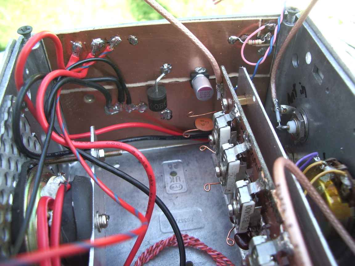
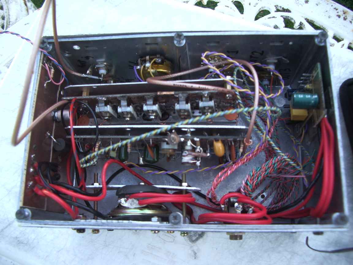
Yet to come, some images of my WWV timebase.
back to homepage
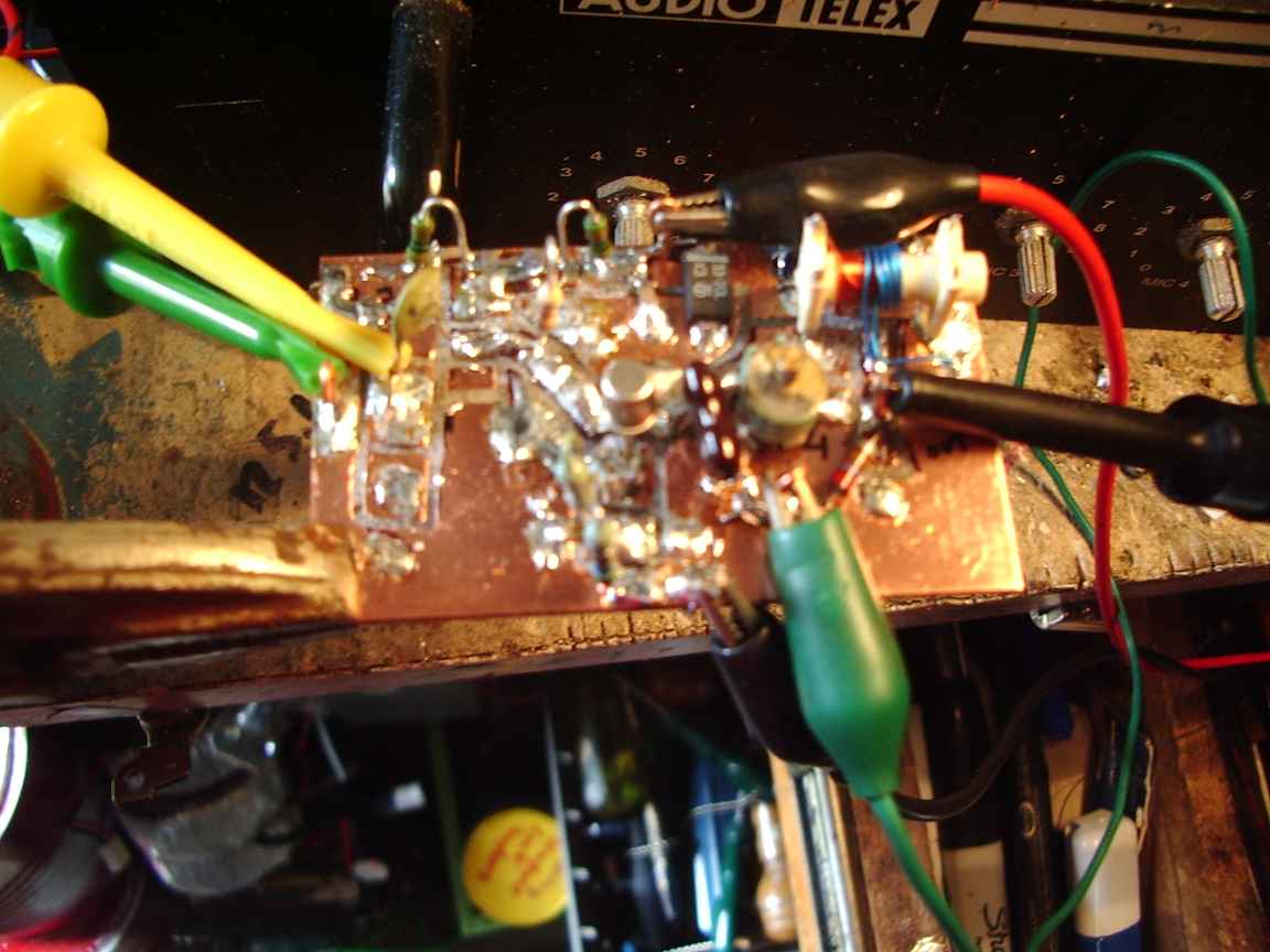 | 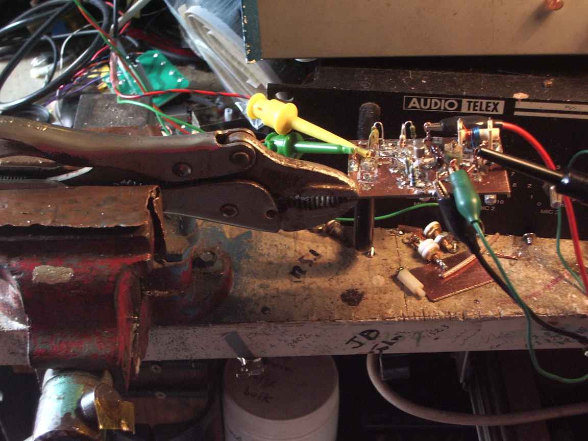 | 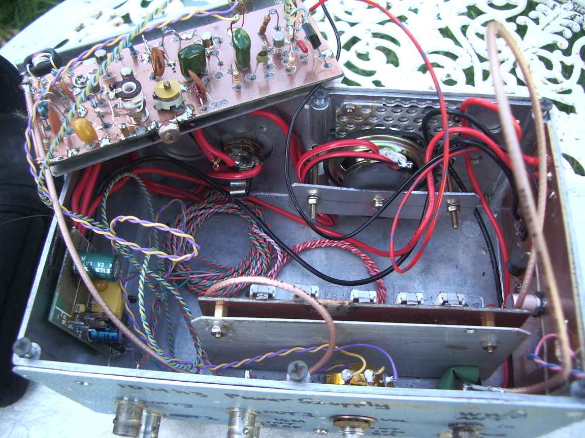 |
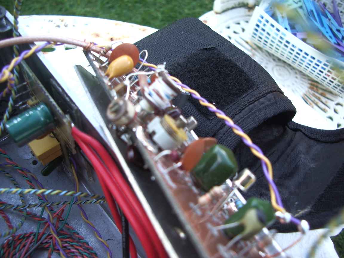
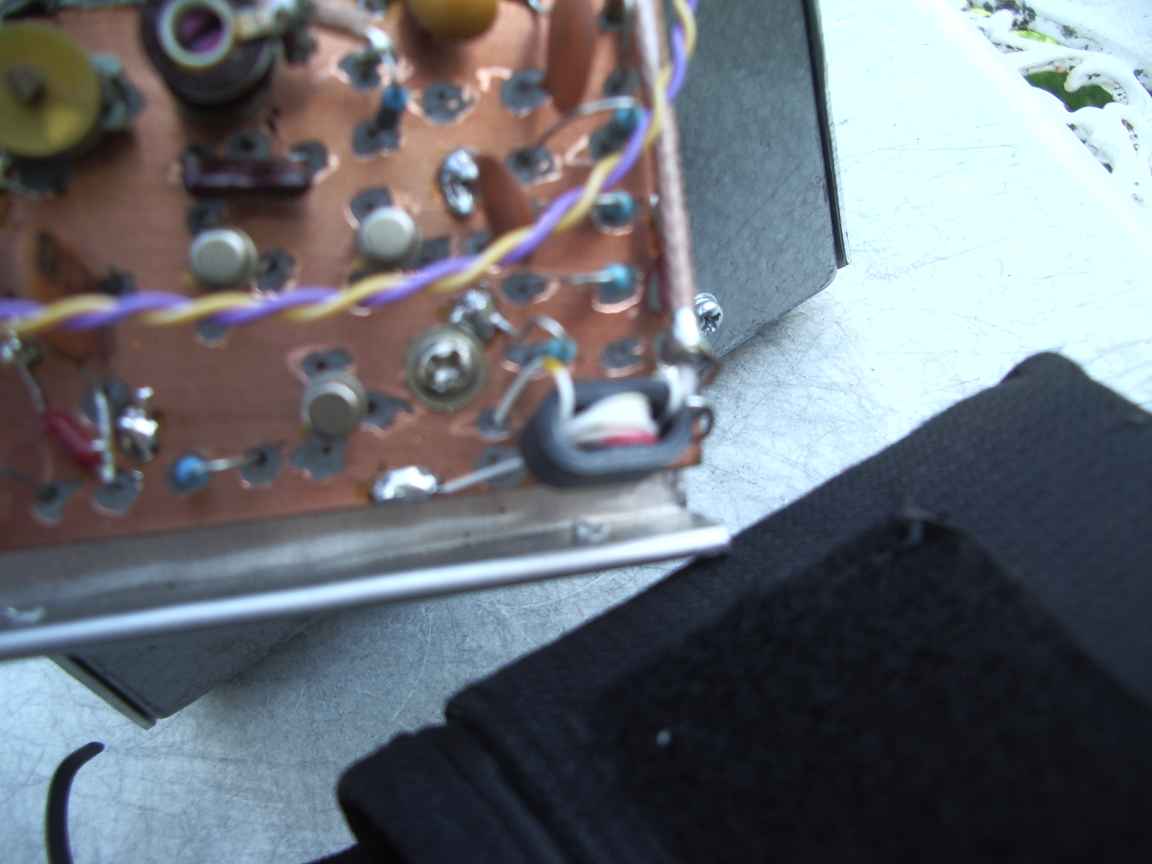
| post filter amplifier | howto hold a small circuit board ! | |
 |  | |
 |  |  |
 |  | 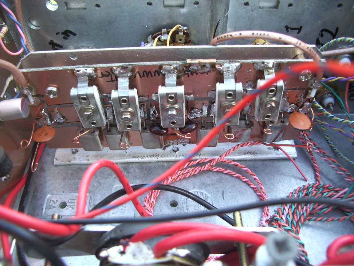 |
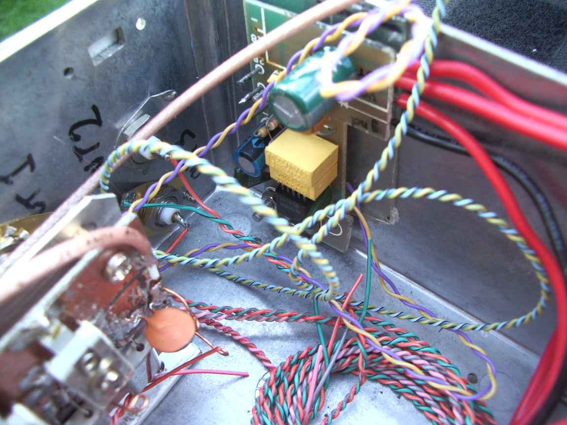
| a hueristically tuned 6 element crystal ladder filter. Twiddle the knobs untill it works ! |

